Drive system of synchronous motor
A synchronous motor and drive system technology, applied in motor control, AC motor control, electronic commutation motor control, etc., can solve the problem of inability to obtain position information, and achieve the effects of reducing noise, reducing vibration, and shortening starting time.
- Summary
- Abstract
- Description
- Claims
- Application Information
AI Technical Summary
Problems solved by technology
Method used
Image
Examples
no. 1 approach
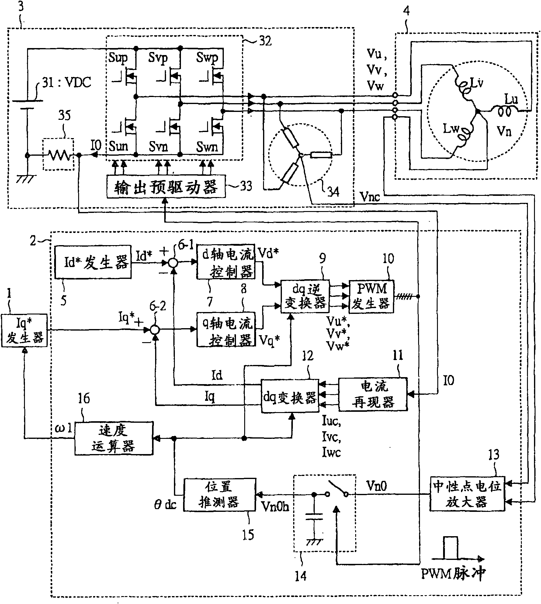
[0061] figure 1 It is a block diagram of the structure of the motor drive system of 1st Embodiment of this invention.
[0062] The purpose of this motor drive system is to drive a permanent magnet motor (three-phase synchronous motor) 4 . If roughly distinguished, the motor drive system includes: Iq * A generator 1, a controller 2, an inverter 3 including an inverter main circuit 32 and a single-branch current detector 35, and a permanent magnet motor 4 as a driving object.
[0063] Iq * Generator 1 generates a current command Iq equivalent to the torque of the motor * circuit. The Iq * The generator 1 is a higher-level controller than the controller 2 . Usually, the configuration is such that the required current command Iq is generated while observing the actual speed ω. * , so that the rotational speed of the permanent magnet motor 4 becomes a predetermined speed. Iq * The output of the generator is the current command Iq * is output to the subtractor 6-2 in the c...
no. 2 approach
[0119] Next, a second embodiment of the present invention will be described.
[0120]In the first embodiment, the reference level Vh is set, compared with the neutral point potential Vn0h, and the phase is updated when the comparison result exceeds a predetermined value. The reference level Vh at this time is a fixed value.
[0121] If the reference level Vh is a fixed value, the scale of the phase information expressed in electrical angle is 60 degrees, which is too low resolution for an ideal sine wave current to drive a permanent magnet motor. The second embodiment aims to solve this problem.
[0122] Figure 9 It is a block diagram of the configuration of the position estimator 15B of the second embodiment. In this embodiment, a position estimator 15B is used instead of the position estimator 15 of the first embodiment.
[0123] The position estimator 15B is composed of a switch 154 , a first memory 155 , a second memory 156 , a position estimator 157 , and a neutral p...
no. 3 approach
[0130] Next, a third embodiment of the present invention will be described.
[0131] In the first and second embodiments, a normally operating PWM signal is used, and the neutral point potential is detected in synchronization with the PWM signal to obtain position information. As described above, the fluctuation of the neutral point potential depends on the magnetic circuit characteristics inside the permanent magnet motor 4 . Therefore, the characteristics of the permanent magnet motor 4 are greatly different depending on the specifications such as capacity and rotational speed. It is also considered that the detection sensitivity of the position information is insufficient depending on the structure of the motor.
[0132] This embodiment solves the above-mentioned problems. In this embodiment, the detection pulse of the neutral point potential is intentionally inserted to generate an isoelectric period insertion sampling period, and the neutral point potential is observed ...
PUM
 Abstract
Description
Claims
Application Information
 - R&D
- Intellectual Property
- Life Sciences
- Materials
- Tech Scout
- Unparalleled Data Quality
- Higher Quality Content
- 60% Fewer Hallucinations
Browse by: Latest US Patents, China's latest patents, Technical Efficacy Thesaurus, Application Domain, Technology Topic, Popular Technical Reports.
© 2025 PatSnap. All rights reserved.Legal|Privacy policy|Modern Slavery Act Transparency Statement|Sitemap|About US| Contact US: help@patsnap.com


