Hybrid power drive system and drive method thereof

A technology of a drive system and a drive method, which is applied to the arrangement of multiple different prime movers of a hybrid vehicle, a power plant, and a general power plant, and can solve problems such as a single drive mode, low energy utilization rate, and increased body weight , to achieve the effect of improving fuel utilization, improving energy utilization and reducing exhaust emissions

Inactive Publication Date: 2010-03-31
BYD CO LTD
View PDF1 Cites 21 Cited by
  • Summary
  • Abstract
  • Description
  • Claims
  • Application Information

AI Technical Summary

Problems solved by technology

[0004] However, in the above-mentioned driving system, on the one hand, the power transmission mechanism 11 for transmitting the power of the engine 1 to the reduction gear 6 has a complex structure, including not only a clutch, but also a torque converter and another reduction gear, so As a result, the structure of the entire drive system is complicated, which not only brings inconvenience to the overall layout of the system, but also increases the weight of the vehicle body
On the other hand, when the power of the engine 1 is directly input to the reduction gear 6 through the power transmission mechanism 11, it will drive the motor 5 to idle, and the engine 1 will also drive the generator 3 to idle, so certain energy loss will be generated.
In addition, the driving mode of the drive system is single, and the effective utilization rate of energy is low, which cannot meet the power requirements of various complex working conditions when the vehicle is actually driving.

Method used


Image

  • Hybrid power drive system and drive method thereof
  • Hybrid power drive system and drive method thereof
  • Hybrid power drive system and drive method thereof

Examples


Embodiment 1

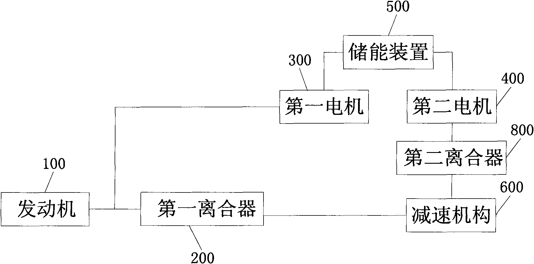
[0023] Embodiment one: if figure 2 As shown, the hybrid drive system provided by the present invention includes: an engine 100 , a first clutch 200 , a first motor 300 , a second motor 400 , an energy storage device 500 , and a reduction mechanism 600 . The engine 100 is connected to the reduction mechanism 600 through the first clutch 200, the engine 100 is connected to the first motor 300, the energy storage device 500 is electrically connected to the first motor 300 and the second motor 400 respectively, and the drive system It also includes a second clutch 800 through which the second motor 400 is connected to the reduction mechanism 600 .

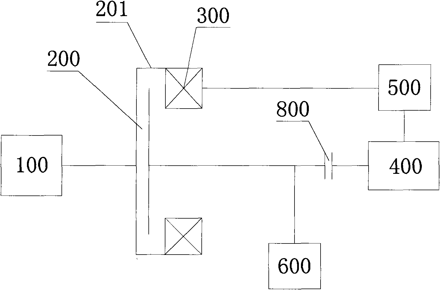
[0024] like image 3 As shown, as a preferred mode of this embodiment, in the hybrid drive system, the first clutch 200 has a first clutch cover 201, and the engine 100 communicates with the first motor 300 through the first clutch cover 201 connected.

[0025] Wherein, the engine 100 may be a gasoline engine, a diesel engine, or o...

Embodiment 2

[0064] Embodiment two: if Figure 11 As shown, the hybrid drive system provided by this embodiment includes: an engine 100 , a first clutch 200 , a first motor 300 , a second motor 400 , a third clutch 900 , an energy storage device 500 , and a reduction mechanism 600 . The engine 100 is connected to the reduction mechanism 600 through the first clutch 200, the energy storage device 500 is electrically connected to the first motor 300 and the second motor 400 respectively, and the second motor 400 is connected to the reduction mechanism 600. The engine 100 is connected with the first motor 300 through the third clutch 900 .

[0065] It can be seen that the difference between this embodiment and Embodiment 1 lies in the position setting of the clutches, and as an equivalent replacement of the clutches in Embodiment 2, a double clutch can be used to replace the first clutch 200 in this embodiment And the third clutch 900, this is an equivalent replacement that can be easily mad...

Embodiment 3

[0070] Embodiment three: as Figure 12 As shown, the hybrid drive system provided by this embodiment includes: an engine 100, a first clutch 200, a second clutch 800, a first motor 300, a second motor 400, a third clutch 900, an energy storage device 500, and a reduction mechanism 600. Wherein the engine 100 is connected to the reduction mechanism 600 through the first clutch 200, the energy storage device 500 is electrically connected to the first motor 300 and the second motor 400 respectively, and the second motor 400 is connected to the reduction mechanism through the second clutch 800 600 , the engine 100 is connected to the first motor 300 through the third clutch 900 .

[0071] The hybrid drive system in this embodiment includes the first clutch 200, the second clutch 800 and the third clutch 900 at the same time, which not only saves the switch unit 501, but prevents the engine 100 from driving the first motor 300 when the first motor 300 is not required to continue w...


PUM


Abstract

The invention provides a hybrid power drive system and a drive method thereof. The drive system comprises an engine, a first clutch, a second clutch, a third clutch, a first motor, a second motor, anenergy storing device and a decelerating mechanism. The engine is connected with the decelerating mechanism by the first clutch. The energy storing device is electrically connected with the first motor and the second motor respectively. The second motor is connected with the decelerating mechanism by the second clutch. The engine is connected with the first motor by the third clutch. The drive method comprises the step of controlling the drive system to be in the pure electric working condition, series-connection working condition, hybrid working condition, three-power source working condition, engine working condition or brake working condition in accordance with the required power of the drive system and the energy storing state of the energy storing device. The drive system provided bythe invention has simple structure, and the drive method gives priority to motor drive and can flexibly control the drive system to be in various working modes so as to meet the requirement of actualrunning.

Description

technical field [0001] The invention relates to a hybrid driving system and a driving method thereof. Background technique [0002] At present, due to its excellent performance in energy saving and environmental protection, hybrid electric vehicles have gradually become the development direction of the automobile industry. A kind of hybrid drive system is disclosed in CN1118387C, such as figure 1 As shown, it includes an engine 1, a generator 3 connected to an output shaft 2 of the engine 1, a battery 4 for storing electric power generated by the generator 3, an electric motor 5 driven by the battery 4, and an output shaft 2 of the engine 1 The connected power transmission mechanism 11, and the reduction gear 6 connected with the electric motor 5 and the power transmission mechanism 11, the output of the reduction gear 6 will finally be transmitted to the wheels. [0003] The driving method of the above-mentioned driving system is that during the normal running of the vehi...

Claims


Application Information

Patent Timeline
Patent Type & Authority Applications(China)
IPC IPC(8): B60K6/20B60K6/387B60K6/28B60K6/442
CPCY02T10/6234Y02T10/62
Inventor 罗红斌任毅杨胜麟王涛
Owner BYD CO LTD
Why Eureka
Try Eureka