Active clamping forward-flyback converter

A flyback converter and clamping technology, applied in the field of converters, can solve the problems of power range, input and output voltage variation range limitations, restrictions, etc., to improve efficiency, reduce voltage stress, and reduce reverse steady-state voltage. Effect

Active Publication Date: 2010-04-07
SANTAK ELECTRONICS SHENZHEN
View PDF3 Cites 36 Cited by
  • Summary
  • Abstract
  • Description
  • Claims
  • Application Information

AI Technical Summary

Problems solved by technology

However, the voltage stress of the switch tube on the primary side of the switching power supply circuit is still the same as that of the circuit in US6262897B1, which will change with the load condition, and will shift to a high level when it is fully loaded, and has not fundamentally overcome the typical resonance technology. Therefore, its possible power range, input and output voltage variation range is limited
In a

Method used


Image

  • Active clamping forward-flyback converter
  • Active clamping forward-flyback converter
  • Active clamping forward-flyback converter

Examples


specific Embodiment approach 1

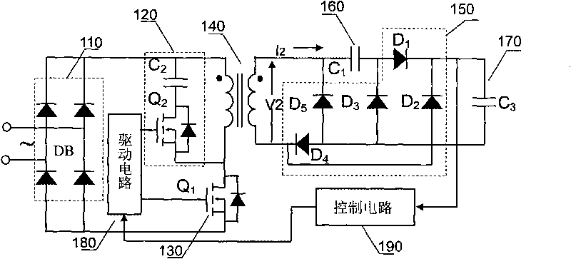
[0036] a kind of like Figure 1~6 The shown active clamp forward-flyback converter includes an input circuit 110, a switch tube drive circuit 180, an inverter switch tube 130, an isolation transformer 140, a primary side clamp resonant circuit 120, a secondary rectifier circuit 150, a secondary A staged direct voltage dividing capacitor 160 , an output filter capacitor 170 , and a voltage control circuit 190 .

[0037] The input circuit 110 is used to rectify the alternating voltage. Because it is not connected to a large-capacity input filter capacitor, it can better follow the input voltage to ensure the power factor (Power Factor, referred to as PF) and total harmonic content (Total Harmonics Distortion, referred to as THD) of the input power supply

[0038] The inverter circuit is composed of an inverter switch tube Q1 and an isolation transformer 140 , and the primary-side clamp resonant circuit 120 is composed of a clamp capacitor C2 , a clamp switch tube Q2 and a trans...

specific Embodiment approach 2

[0069] a kind of like Figure 7 The shown active clamp forward-flyback converter has the same basic circuit composition and beneficial effects as the specific embodiment 1, the difference is: the series branch composed of the clamp switch tube and the primary side clamp capacitor is connected in series to the isolated Between the beginning of the primary winding on the primary side of the transformer and the negative terminal of the DC power supply, rather than in parallel with the primary winding on the primary side of the isolation transformer.

specific Embodiment approach 3

[0070] a kind of like Figure 8 The shown active clamp forward-flyback converter has the same basic circuit composition and beneficial effects as the first embodiment, the difference is that the secondary winding of the isolation transformer 140 has an additional winding L0 extending outwards at its starting end. secondary windings, rather than separate secondary windings.


PUM


Abstract

The invention discloses an active clamping forward-flyback converter, which is provided with a primary side clamping resonant circuit comprising a series branch consisting of a clamping switching tube and a primary side clamping capacitor, wherein the series branch is connected with an original-level winding of the primary side of an isolation transformer in parallel or is connected in serial between a start end of the original-level winding of the primary side of the isolation transformer and a negative terminal of a direct current power supply; and a contravariant switching tube works in a ZVS state, and a secondary rectification circuit is one of a forward-flyback working rectification loop and a flyback working rectification loop. The active clamping forward-flyback converter can enter two different operation modes to achieve a large adjustment range of input and output voltages, reduce reverse steady-state voltages and reverse recovery resonance voltage spikes of a primary side switching tube and a secondary rectifier diode and the voltage stress and the switching loss of the primary side switching tube, and improve the efficiency. The active clamping forward-flyback converter is particularly suitable to be widely applied in the occasions with a very wide input voltage fluctuation range and a wide and high output voltage, in which semiconductors cannot withstand high voltages.

Description

technical field [0001] The invention relates to a converter, in particular to a wide range non-output inductance active clamp forward-flyback converter. Background technique [0002] LLC resonance, active clamp flyback, active clamp forward and their improvement schemes, which belong to soft switching technology, have been widely used in power supplies. U.S. Patent US7301785B2 discloses a switching power supply circuit, which is a further improvement of U.S. Patents US6262897B1 and US6356465B2. By controlling the coupling ratio of the primary and secondary coils of the transformer and the corresponding ratio of the primary and secondary resonance frequencies, the control method solves the problem of US6262897B1 The problem that the voltage stress of the primary switching tube drifts to a high level with the load in the patent also improves the abnormal working condition at a certain load point in US6356465B2 to some extent. However, the voltage stress of the switch tube on ...

Claims


Application Information

Patent Timeline
IPC IPC(8): H02M3/28H02M3/338
Inventor 李伦全顾亦磊王超
Owner SANTAK ELECTRONICS SHENZHEN
Why Eureka
Try Eureka