Digital self-adaptive dead-time control circuit

A dead-time control and self-adaptive technology, applied in the field of electronics, can solve problems such as efficiency, accuracy, response time that cannot meet the expected requirements of dead-time design, large delay time, and accuracy impact.

Inactive Publication Date: 2010-04-14
UNIV OF ELECTRONICS SCI & TECH OF CHINA
View PDF0 Cites 21 Cited by
  • Summary
  • Abstract
  • Description
  • Claims
  • Application Information

AI Technical Summary

Problems solved by technology

However, since the comparator itself has relatively large power consumption, and due to factors such as offset and temperature drift, its own accuracy will also be affected, and the inherent delay time is also relatively large.
Therefore, this method will be difficult to implement, and the efficiency, accuracy, and response time cannot meet the expected requirements of dead time design.

Method used


Image

  • Digital self-adaptive dead-time control circuit
  • Digital self-adaptive dead-time control circuit
  • Digital self-adaptive dead-time control circuit

Examples


Embodiment Construction

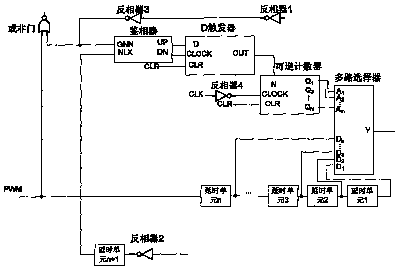
[0036] A digital adaptive dead time control circuit, such as figure 1 As shown, it is composed of a phase detector, a D flip-flop, a reversible counter, an n-to-1 multiplexer, (n+1) delay units, two low flip-level inverters, and two ordinary inverters. A NOR gate is formed. The inverting output terminal of the low inversion level inverter 2 is connected to the NLX input terminal of the phase detector through the (n+1)th delay unit, and the inverting output terminal of the low inversion level inverter 1 is connected to the common inverter 3 The GNN input terminal of the phase detector; the UP output terminal of the phase detector is connected to the D input terminal of the D flip-flop, and the DN output terminal of the phase detector is connected to the CLOCK input terminal of the D flip-flop; the clearing terminal CLR of the D flip-flop is connected to External clearing signal, the OUT output terminal of the D flip-flop is connected to the N input terminal of the reversible c...


PUM


Abstract

The invention relates to a digital self-adaptive dead-time control circuit, belonging to the electronic technical field and relating to an integrated circuit technology and power conversion and motor-driving circuits which adopt a synchronous rectification technology. The digital self-adaptive dead-time control circuit comprises a phase discriminator, a D-trigger, a reversible counter, an n-to-1 multiple selector, (n+1) delay units, two low-flip level inverters, two common inverters and an NOR gate. The phase demodulation comparison of starting signals of an NMOS transistor SR is continued to control the reversible counter to carry out add-subtract count, so as to adjust a delay time unit and control the multiple selector to start the NMOS transistor SR in a suitable clock to further realize the self-adaptive adjustment of dead time. The invention not only avoids the simultaneous conduction of two power tubes caused by overshot dead time, but also avoids the conduction of a body diode caused by overlong dead time, thereby decreasing additional loss caused by the unsuitably set dead time and improving the whole efficiency of the power converter.

Description

technical field [0001] The invention belongs to the field of electronic technology, and relates to integrated circuit technology, power conversion and motor drive circuit using synchronous rectification technology. Background technique [0002] A power conversion circuit with a DC output usually requires a rectifier circuit to rectify its output. Usually the rectifier element in the rectifier circuit uses a rectifier diode. The rectifier diode does not require a special control circuit, as long as the input voltage is high enough, it will be turned on. However, the efficiency of this rectification circuit is relatively low, which is caused by the relatively large conduction voltage drop of the rectification diode itself. The conduction voltage drop of the fast recovery diode is 1.0-1.2V, and even a Schottky diode with a relatively low conduction voltage drop will have a conduction voltage drop of 0.3-0.4V. The loss of efficiency due to its own forward voltage drop is part...

Claims


Application Information

Patent Timeline
Patent Type & Authority Applications(China)
IPC IPC(8): H03K19/003H03K5/00H02M7/04H02M3/155
Inventor 罗萍甄少伟高丽祝晓辉
Owner UNIV OF ELECTRONICS SCI & TECH OF CHINA
Why Eureka
Try Eureka