System for automatically extinguishing fire in long tunnel and extinguishing method thereof

An automatic fire extinguishing system and tunnel technology, applied in earthwork drilling, fire prevention, safety devices, etc., can solve the problems of high cost of gas fire extinguishing system, difficulty in controlling fire with fire hydrants, environmental and human hazards, etc., and achieve specific surface area and density High, good fire extinguishing effect, the effect of preventing heat radiation

Inactive Publication Date: 2011-11-23
DALIAN MARITIME UNIVERSITY
View PDF0 Cites 0 Cited by
  • Summary
  • Abstract
  • Description
  • Claims
  • Application Information

AI Technical Summary

Problems solved by technology

The fire extinguisher uses a gaseous fire extinguishing agent, which has low fire extinguishing efficiency and poor effect, and has certain harm to the environment and human body. After the fire is extinguished, the recovery of the facilities is slow, and the gas fire extinguishing system is expensive and the maintenance cost is high.
The standard distance between fire hydrants is 50m. Tunnel fires are mostly caused by vehicle fuel or flammable goods on board, and are likely to be accompanied by deflagration. It is difficult for fire hydrants to control such fires.
It can be seen that the main problems of the existing fire extinguishing system are low fire extinguishing efficiency, poor fire extinguishing effect, low degree of automation, and certain harm to the environment and human body.

Method used


Image

  • System for automatically extinguishing fire in long tunnel and extinguishing method thereof
  • System for automatically extinguishing fire in long tunnel and extinguishing method thereof
  • System for automatically extinguishing fire in long tunnel and extinguishing method thereof

Examples


Embodiment Construction

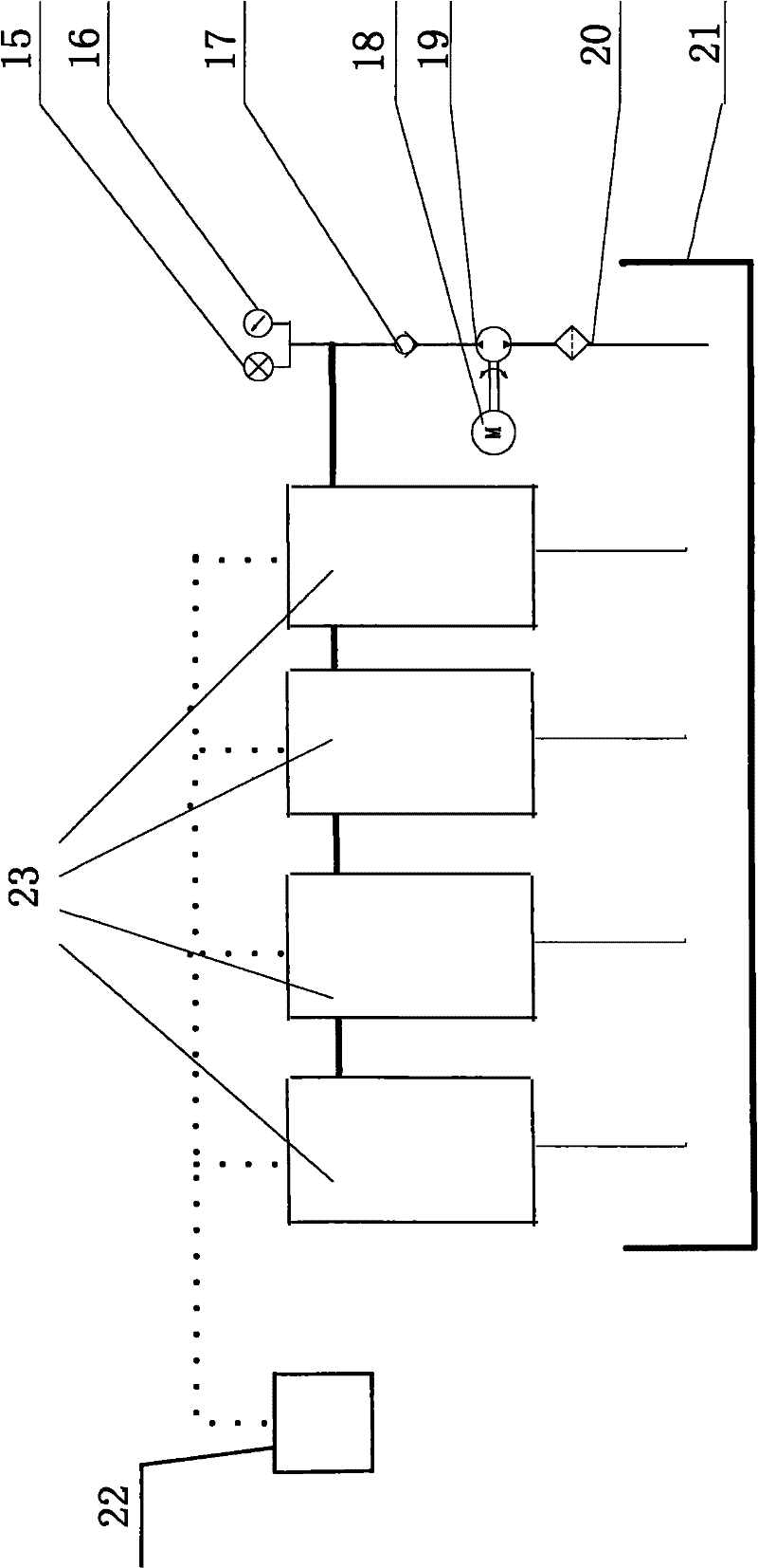
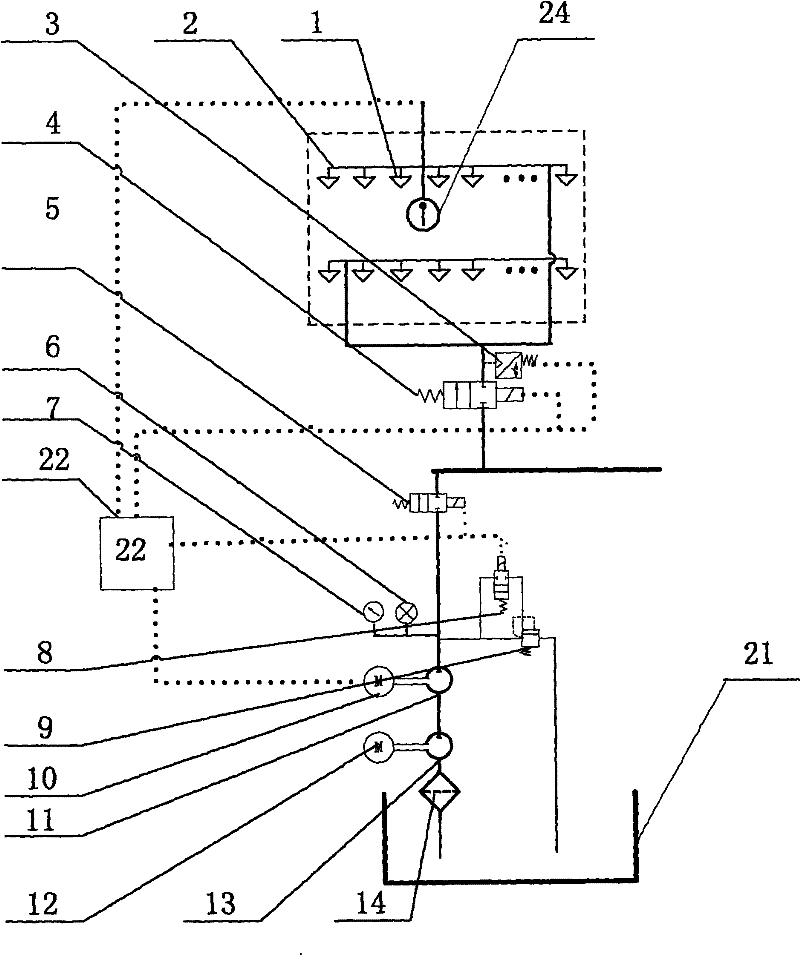
[0025] The present invention will be further described below in conjunction with accompanying drawing. Such as Figure 1-2 As shown, a long tunnel automatic fire extinguishing system includes an emergency pressure transmitter 15, an emergency pressure gauge 16, an emergency one-way valve 17, an emergency motor 18, an emergency pump 19, an emergency filter 20, a water tank 21, a PLC controller 22 and three More than one single-zone fire extinguishing unit 23, one end of the emergency filter 20 is connected to the water tank 21 through a pipeline, and the other end is connected to the emergency pump 19 through a pipeline, and the emergency motor 18 is connected to the emergency pump 19. The emergency pressure transmitter 15 and the emergency pressure gauge 16 are all installed on the high-pressure pipe at the water outlet of the emergency pump 19, and the emergency pump 19 is respectively connected to each single-zone fire extinguishing unit 23 through the high-pressure pipe, an...


PUM


Abstract

The invention discloses a system for automatically extinguishing fire in a long tunnel and an extinguishing method thereof. The system comprises an emergency pipeline, a water tank, a PLC (programmable logic controller) and more than three single-zone extinguishing units, wherein the PLC is connected with each single-zone extinguishing unit via control cables respectively; each single-zone extinguishing unit comprises a nozzle, a pure-water high-pressure pump and an ultrahigh-pressure pipeline; the pure-water high-pressure pump is capable of outputting high-pressure water flow with the pressure intensity being higher than 14MPa; and the nozzle is a water-mist nozzle combining multiple nozzles. The method comprises the following steps: detecting; giving a fire alarm; and controlling the water supply, mist-spraying, backwater and the like by the PLC. The tiny fog droplets formed by the ultrahigh-pressure water flowing through the dedicated water-mist nozzle is adopted to extinguish fire, the tiny fog droplets can be rapidly vaporized when meeting the high-temperature flame and the volume thereof can expand by more than 1,700 times so as to greatly reduce the oxygen concentration of a protection zone and have the strong effects of cooling by vaporization and suffocation by oxygen isolation; and meanwhile, the fog droplets can surround the fire source and further prevent heat radiation and diffusion, thereby achieving the purpose of rapidly extinguishing fire.

Description

technical field [0001] The invention relates to a tunnel fire-fighting equipment, in particular to an automatic fire-extinguishing system for a long tunnel and a fire-extinguishing method thereof. Background technique [0002] With the rapid development of my country's national economy, the role of railways and highways as a transportation hub is becoming more and more significant. As an important part of railways and highways, tunnels play an increasingly important role in transportation research. Tunnels are places where vehicles pass through. With the development of economy, the density of vehicles passing through tunnels is increasing. Once a fire occurs, it is very easy to cause serious consequences such as mass casualties and property losses. Due to the complex geometric structure of the tunnel, poor ventilation conditions, generally strong chemical reactions of combustion materials, and intense heat transfer, the tunnel fire spreads quickly, the temperature rises rapi...

Claims


Application Information

Patent Timeline
Patent Type & Authority Patents(China)
IPC IPC(8): E21F5/00E21F5/04
Inventor 弓永军王祖温衣正尧何光华
Owner DALIAN MARITIME UNIVERSITY
Why Eureka
Try Eureka