Biomass gasifier with multiple fire grates
A gasification furnace and biomass technology, applied in the field of gasification furnaces, can solve the problems of controlling the speed of ash discharge, difficulty in bridging, material leakage, etc., and achieve the effects of improving work efficiency, enhancing gas production capacity, and avoiding accumulation
- Summary
- Abstract
- Description
- Claims
- Application Information
AI Technical Summary
Problems solved by technology
Method used
Image
Examples
Embodiment 1
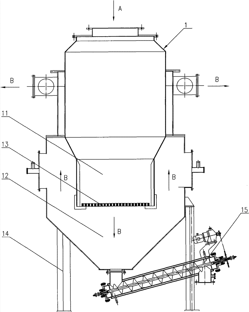
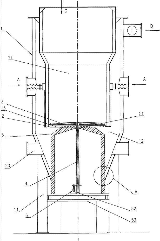
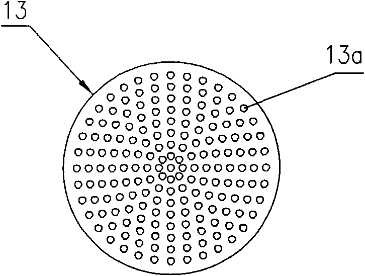
[0044] Such as Figure 2-5 As shown, a multi-grate biomass gasifier 1 includes a furnace body 11, a grate 13, an ash chamber 12, a support 14 for supporting the gasifier 1, and an ash discharge mechanism. The grate 13 is made of alloy steel, Its surface is laid with insulating material, and the insulating material adopts refractory cement. The grate 13 is horizontally arranged in the furnace body 11, the ash chamber 12 is located below the furnace body 11, and through holes 13a are distributed on the grate 13. The through holes 13a are The circular holes distributed in the center, the outer contour of the grate 13 is smaller than the contour of the inner wall of the furnace body 11, there is a gap between its edge and the inner wall of the furnace body 11, forming the ash discharge hole 2; To dial the ash slag on the grate 13 into the ash-discharging mechanism in the ash discharge hole 2, the ash-discharging mechanism is connected with an ash-discharging driving mechanism, and...
Embodiment 2
[0052] Such as Figure 6-13 As shown, the difference between this embodiment and Embodiment 1 is that a grate through hole adjustment mechanism is provided, that is, a rotatable grate hole adjustment plate 19 is set below the grate 13, and the grate 13 is connected to the grate hole. The through holes on the adjusting plate 19 are fan-shaped holes distributed in the center, and a grate support structure for supporting the grate 13 is provided between the grate hole adjusting plate 19 and the grate 13, and the grate hole adjusting plate 19 passes through the shaft. The bearing is installed on the top surface of the shield 5, and the grate hole adjusting plate 19 is provided with a through hole 19a corresponding to the through hole 13a on the grate 13, leaving a gap between the grate hole adjusting plate 19 and the grate 13. There is an appropriate rotation gap so that there is relative movement between the two. A rotating shaft 23 is provided in the middle of the grate hole adj...
Embodiment 3
[0057] The difference between this embodiment and Embodiment 2 is that the lifting device is omitted, the edge of the grate is fixedly connected with the inner wall of the furnace body, and the edge of the grate 13 has an annular through hole as the ash discharge hole.
[0058] As other implementations, the grate hole adjusting plate can also be arranged above the grate in Example 1, and at the same time be located below the ash-pushing stick, the rotating shaft of the grate hole adjusting plate is coaxial with the rotating shaft of the ash-pushing stick, and the grate The rotating shaft of the hole adjusting plate passes downward through the center hole of the grate and is vertically installed in the installation hole on the top surface of the guard through the axial bearing. In this embodiment, the grate support structure can be changed to be arranged in the grate hole Between the lower surface of the adjusting plate and the upper surface of the grate; when no lifting device ...
PUM
 Abstract
Description
Claims
Application Information
 - R&D
- Intellectual Property
- Life Sciences
- Materials
- Tech Scout
- Unparalleled Data Quality
- Higher Quality Content
- 60% Fewer Hallucinations
Browse by: Latest US Patents, China's latest patents, Technical Efficacy Thesaurus, Application Domain, Technology Topic, Popular Technical Reports.
© 2025 PatSnap. All rights reserved.Legal|Privacy policy|Modern Slavery Act Transparency Statement|Sitemap|About US| Contact US: help@patsnap.com


