Device for carrying out optical non-destructive testing on surface of annular inner wall

A non-destructive testing, circular technology, applied in the direction of measuring devices, material analysis through optical means, scientific instruments, etc., can solve the problems of out-of-focus, large field of view and high sensitivity at the same time, and the sensitivity of digital shearing speckle interference technology and the resolution can not be further improved to achieve the effect of eliminating defocusing phenomenon, increasing the area and improving the sensitivity

Inactive Publication Date: 2010-05-05
NORTHWESTERN POLYTECHNICAL UNIV
View PDF2 Cites 23 Cited by
  • Summary
  • Abstract
  • Description
  • Claims
  • Application Information

AI Technical Summary

Problems solved by technology

Therefore, non-destructive testing based on area array CCD cannot meet the requirements of large field of view and high sensitivity at the same time.
In addition, if the surface of the material to be tested has large fluctuations, exceeding the depth of field limit of the ima...

Method used


Image

  • Device for carrying out optical non-destructive testing on surface of annular inner wall
  • Device for carrying out optical non-destructive testing on surface of annular inner wall

Examples


Embodiment Construction

[0029] Now in conjunction with embodiment, accompanying drawing, the present invention will be further described:

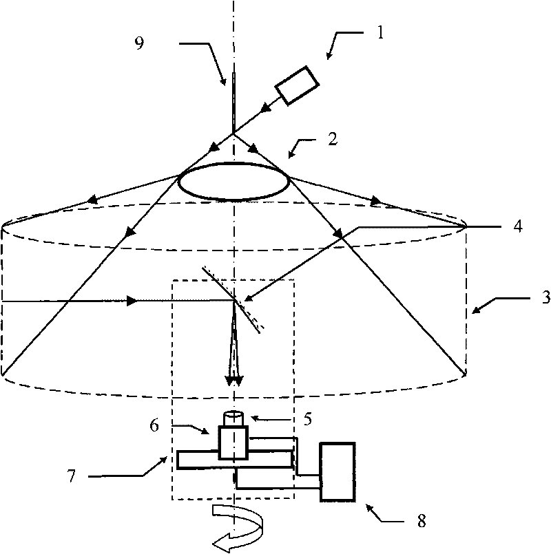
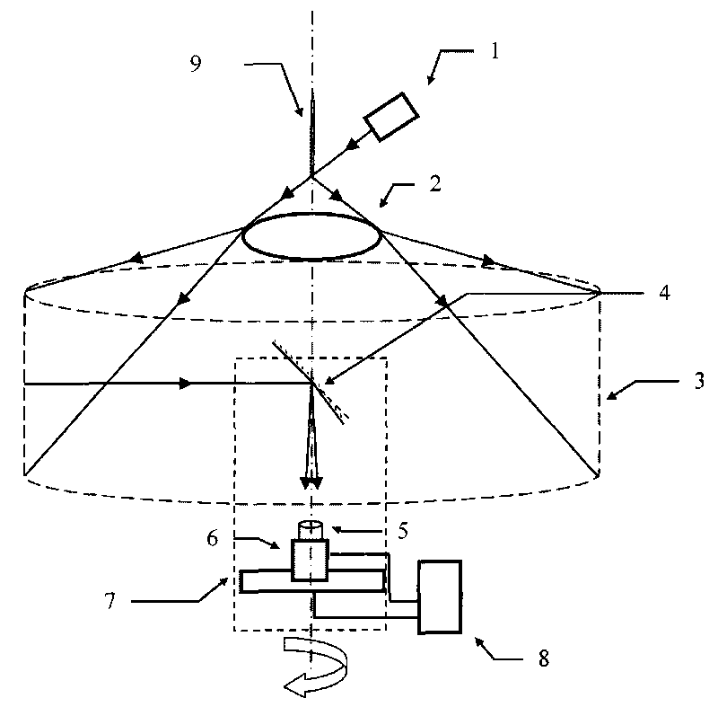
[0030] This embodiment includes a laser 1 , a beam expander 2 , a shearing element 4 , an imaging device 5 , a linear array CCD 6 , a rotary table 7 , a computer 8 and a thin glass rod 9 .

[0031] In the present embodiment, the laser adopts a helium-neon laser; the annular inner wall of an object to be tested 3 is the tire inner wall; the diameter of the thin glass rod 9 is 8mm, which is arranged at a position where the axis of the tire is less than 90mm from the center of the tire, and is parallel to The thin glass rod placed on the axis of the tire can also be replaced by an optical fiber; the laser 1 is located on one side of the thin glass rod, and the thin beam emitted by the laser forms an angle of 1° to 90° with the axis of the glass rod, and the light beam irradiates the end of the glass rod near the tire. The beam expander 2 adopts a bracelet-shaped ann...


PUM

PropertyMeasurementUnit
Diameteraaaaaaaaaa

Abstract

The invention relates to a device for carrying out optical non-destruction testing on the surface of an annular inner wall, which is characterized in that a fine glass rod, a beam expanding device, a shearing element, an imaging device, a linear array CCD and a rotary table are sequentially arranged on an axis line of the tested annular inner wall; the sharing element, the imaging device and the linear array CCD are fixed on the rotary table, and a primary optical axis of the linear array CCD is coincided with a rotation axis; the fine glass rod is arranged on the axis line of the annular inner wall with the distance of less than 200mm to the center of the annular inner wall and arranged in parallel with the axis line of the annular inner wall; an optical axis of a laser is placed by leading the angle between the optical axis and the central axis line of the glass rod to be 0.01 degree-20 degrees; and image signals collected by the linear array CCD are outputted to a computer, and a control signal of the computer is outputted to the rotary table for controlling the rotation of the rotary table. The linear array CCD is utilized for push-broom, a mobile track of a micro-displacement platform is designed according to the surface of a tested sample, and a speckle pattern obtained by push-broom along the mobile track can eliminate the defocus phenomenon of a speckle image and improve the sensitivity of defect detection.

Description

technical field [0001] The invention relates to a device for optical non-destructive testing of the surface of an annular inner wall, which belongs to the technical field of optical non-destructive testing. Background technique [0002] Digital shear speckle interferometry is a laser-based full-field, non-contact measurement of surface deformation (displacement or strain). A shearing mirror with a small wedge angle is placed in front of the imaging lens, so that a point on the surface of the object produces a pair of two images with a small misalignment on the image plane. Since the surface of the object is illuminated by the laser, the image caused by the misalignment The two clipped images interfere with each other to form a clipped speckle field containing a random interference pattern. The dislocation images interfere with each other on the image plane to form a speckle interference image, which is collected by the CCD into the computer through the image card, and the t...

Claims


Application Information

Patent Timeline
IPC IPC(8): G01N21/954G01N21/45
Inventor 赵建林邸江磊孙伟伟
Owner NORTHWESTERN POLYTECHNICAL UNIV
Why Eureka
Try Eureka