
Shunting-type isothermal sulfur-tolerant conversion process and equipment thereof

A sulfur-resistant conversion and split-flow technology, which is applied in the chemical industry, sustainable manufacturing/processing, inorganic chemistry, etc., can solve the problems of overheating of the by-product steam of the conversion, large temperature rise of the adiabatic conversion furnace, and excessive steam-to-gas ratio. Achieve the effect of adding less steam, producing the most waste water, and improving the filling factor

Active Publication Date: 2011-11-16
SHANGHAI INT ENG CONSULTING
View PDF1 Cites 2 Cited by
  • Summary
  • Abstract
  • Description
  • Claims
  • Application Information

AI Technical Summary

Problems solved by technology

[0006] One of the technical problems to be solved by the present invention is to overcome the deficiencies in the prior art and provide a new CO split-flow isothermal sulfur-resistant conversion process, which solves the superheating and adiabatic of the by-product steam in the conversion through the upper-flow split type The temperature rise of the converter furnace is too large, the steam-to-gas ratio is too large, and the amount of waste water is too large, etc.
In the process, the forced circulation heat transfer method is adopted to solve the heat transfer problem of large heat release and large heat flux, so as to reduce the temperature of hot spots and adapt to the transformation of high CO gas

Method used


Image

  • Shunting-type isothermal sulfur-tolerant conversion process and equipment thereof
  • Shunting-type isothermal sulfur-tolerant conversion process and equipment thereof
  • Shunting-type isothermal sulfur-tolerant conversion process and equipment thereof

Examples


Embodiment 1

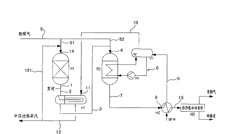
[0047] see figure 1 , figure 1 The split-flow isothermal sulfur-tolerant shift equipment shown is suitable for gas shift with high CO content.

[0048]The split-type isothermal sulfur-resistant shift equipment includes the first shift reactor R1, the second shift reactor R2, the steam superheater H1, the steam drum V1, the boiler feed water preheater H2 and the heat recovery cooling system H3, the first shift reactor R1 is an axial type adiabatic shift reactor or an axial radial type adiabatic shift reactor. The second shift reactor is one of vertical shell-and-tube type, vertical cold-tube type, vertical plate-type, horizontal shell-and-tube type, horizontal cold-tube type, and horizontal plate-type isothermal shift reactor.

[0049] The first shift gas outlet pipe 1 of the first shift reactor R1 is directly connected to the first shift gas inlet pipe 2 of the steam superheater H1, and the first shift gas delivery pipe 3 of the steam superheater H1 is connected to the raw m...

Embodiment 2

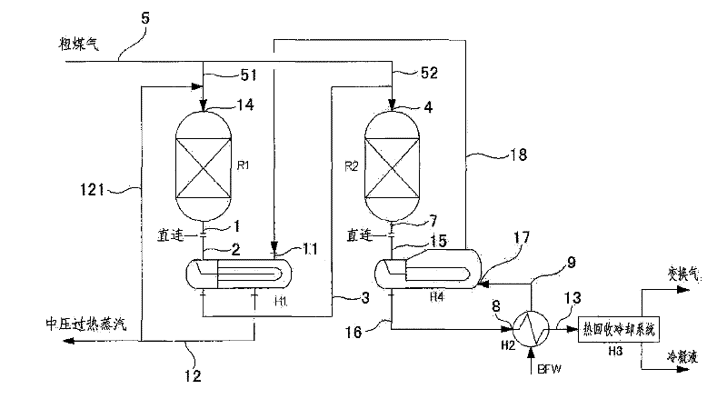
[0060] see figure 2 , figure 2 The split-flow isothermal sulfur-tolerant shift equipment shown is suitable for gas shift with high CO content.

[0061] The split flow isothermal sulfur-resistant shift equipment includes the first shift reactor R1, the second shift reactor R2, the steam superheater H1, the waste heat boiler H4, the boiler feed water preheater H2 and the heat recovery cooling system H3,

[0062] The first shift reactor R1 and the second shift reactor R2 are axial type adiabatic shift reactors or axial radial type adiabatic shift reactors.

[0063] The first shift gas outlet pipe 1 of the first shift reactor R1 is directly connected to the first shift gas inlet pipe 2 of the steam superheater H1, and the first shift gas delivery pipe 3 of the steam superheater H1 is connected to the raw material of the second shift reactor R2 The gas inlet 4 is connected, and the raw gas inlet 4 of the second shift reactor R2 is also connected to the raw gas 5 . The second s...

Embodiment 3

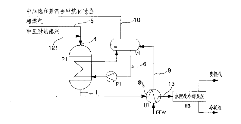
[0069] see image 3 , image 3 The split-flow isothermal sulfur-tolerant shift equipment shown is suitable for gas shift with medium and low CO content.

[0070] The split flow isothermal sulfur resistant shift equipment includes the first shift reactor R1, steam drum V1, boiler feed water preheater H2 and heat recovery cooling system H3,

[0071] The first shift reactor R1 is one of vertical shell-and-tube type, vertical cold-tube type, vertical plate-type, horizontal shell-and-tube type, horizontal cold-tube type, and horizontal plate-type isothermal shift reactor.

[0072] The first shifted gas outlet pipe 1 of the first shift reactor R1 is connected to the inlet 8 of the boiler feed water preheater H2, and the boiler feed water pipe 9 of the boiler feed water preheater H2 is connected to the steam drum V1 and delivered to the steam drum V1 Preheated boiler feed water; the first shift reactor R1 is connected to the steam drum V1 through a forced circulation heat transfer ...


PUM


Abstract

The invention discloses a shunting-type isothermal sulfur-tolerant conversion process. The process comprises the following steps: shunting raw coal gas from exterior into at least two parts; leading overheat stream in the first part of the raw coal gas to increase the temperature to 200-300 DEG C; and then entering a first-stage conversion reaction step to carry out a conversion reaction and generate first conversion gas; and conveying the other part of the raw coal gas to next-stage conversion reaction step to carry out a conversion reaction. The catalyst bed of a shift converter has the advantages of stable temperature, simple control, convenient operation and low output CO content. The invention has the advantages of short conversion flows, few equipment, reduced resistance, great byproduct stream amount, high overheat temperature, stream pressure and heat recovery rate, and the like, thereby achieving the aims of reducing conversion stages, equipment number and resistance fall, decreasing investment, having great byproduct stream amount and high overheat temperature, stream pressure and heat recovery rate, reducing conversion stream consumption and outward wastewater discharge, protecting the environment and easily maximizing the device equipment. The invention also discloses shunting-type isothermal sulfur-tolerant conversion equipment used by the process.

Description

technical field [0001] The invention belongs to the field of gas purification, and relates to a split-type isothermal sulfur-resistant shift process and equipment for coal-based gas, using a Co-Mo wide-temperature sulfur-resistant shift catalyst to make carbon monoxide and water vapor undergo a shift reaction to generate hydrogen and carbon dioxide . The invention is applicable to large and super-large conversion devices such as coal-to-synthetic natural gas, coal-to-synthetic oil, coal-to-mixed alcohol, and coal-to-methanol. Background technique [0002] In recent years, the synthesis gas from coal chemical industry has developed rapidly, and different downstream products have great influence on H in the synthesis gas 2 The requirements for the / CO ratio are different, and the gas composition is generally adjusted by shift reaction. Carbon monoxide (CO) conversion devices play an important role in coal-to-synthetic natural gas, coal-to-synthetic oil, coal-to-mixed alcohol...

Claims


Application Information

Patent Timeline
Patent Type & Authority Patents(China)
IPC IPC(8): C01B3/12
CPCY02P20/10
Inventor 杨震东陆欢庆金力强
Owner SHANGHAI INT ENG CONSULTING
Learn More