Compressed air engine and application thereof

A technology of compressed air and engine, applied in the direction of machine/engine, motor-driven engine, rotorcraft, etc., can solve the problems of obtaining vertical take-off and landing and hovering, power loss, difficult aircraft, etc., to achieve simple structure and reduce construction costs and construction time, installation location and flexible effect of adding or removing replacement

Inactive Publication Date: 2010-05-12
徐林波
View PDF4 Cites 5 Cited by
  • Summary
  • Abstract
  • Description
  • Claims
  • Application Information

AI Technical Summary

Problems solved by technology

This way of traveling has an obvious disadvantage: for rolling friction, the vehicle itself needs to have enough weight; for the rotating impellers of various ships, it is also blocking the fluid while pushing the fluid, which means A large part of the energy is doing useless work
In addition, for the currently widely used engines with crank connecting rods and crankshafts as power output mechanisms, it is necessary to convert the mechanical linear motion of the piston into mechanical rotary motion, which not only makes the structure huge and complicated, but also causes power loss
[0003] In addition, the various jet engines currently used in aircraft are difficult to enable the aircraft to obtain vertical take-off and landing and hovering capabilities

Method used


Image

  • Compressed air engine and application thereof
  • Compressed air engine and application thereof

Examples


Embodiment Construction

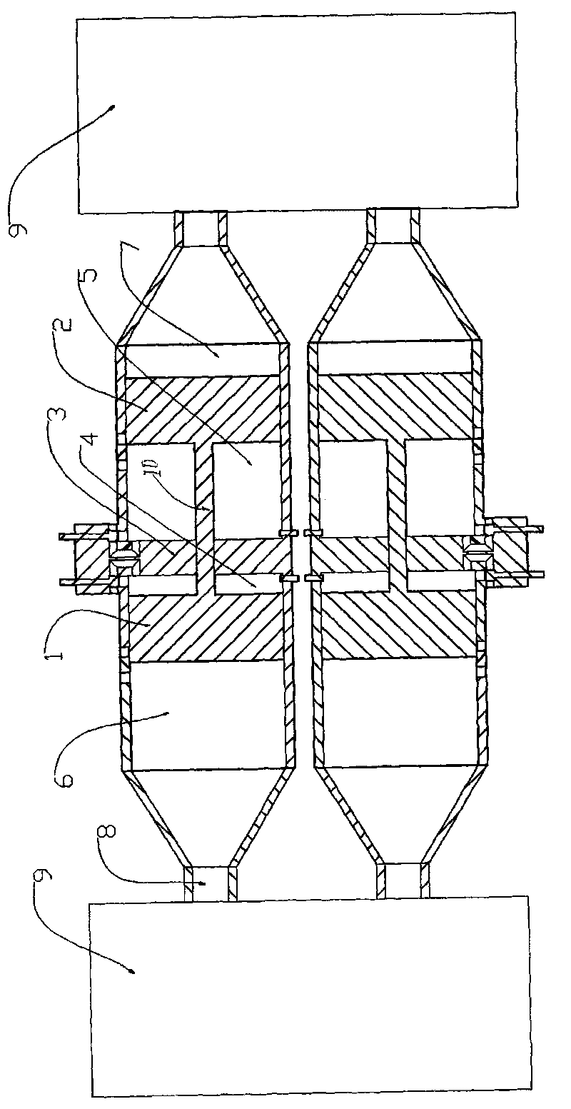
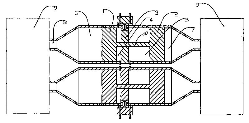
[0018] In the accompanying drawings, the pistons (1) and (2) in the piston engine are spaced at a certain distance and fixedly connected in series; the sealed partition (3) between them divides the cylinder into two combustion chambers (4) and (5) And two air compression chambers (6) and (7), and the pistons (1) and (2) are opposite to each other; when the piston (2) performs suction and power strokes, it drives the piston (1) to exhaust and compression stroke, and vice versa. When the pistons (1) and (2) of the piston engine do work, the air in the two air compression chambers (6) and (7) is continuously pressed into the air storage tank (9) through the check valve (8), and then passed through The nozzles installed in all directions of the moving object are ejected to obtain power.

[0019] In order to increase the gas production per unit time of a single piston engine, the diameters of the pistons (1) and (2) can be increased, or the length of the cylinder and the stroke of...


PUM


Abstract

The invention relates to a compressed air engine and an application thereof, and is characterized in that pistons of a piston engine are used for compressing air into an air storage tank, and an object is driven to move or generate lift force by counter acting force produced by jet of the compressed air. The piston engine has the structure as follows: an air cylinder is divided into two combustion chambers (4) and (5) as well as two air compression chambers (6) and (7) by the two pistons (1) and (2) which are arranged at interval in a certain distance and fixedly connected with each other in series and a sealing partition wall arranged between the two pistons; the pistons (1) and (2) have reverse stroke movement; and gas pressurization is used for driving the pistons to move, so that the two pistons can complete the whole work circulation process in an alternate way.

Description

technical field [0001] The invention relates to a compressed air engine and its application. Background technique [0002] The power output of engines currently used in various means of transportation is almost all in the form of rotating shafts or rotating wheels. Vehicles are propelled by rolling friction between the wheels and the ground or rails; ships are propelled by rotating impellers that propel fluid. This way of traveling has an obvious disadvantage: for rolling friction, the vehicle itself needs to have enough weight; for the rotating impellers of various ships, it is also blocking fluid while pushing fluid, which means A large part of the energy is doing useless work. In addition, for the currently widely used engines with crank connecting rods and crankshafts as power output mechanisms, it is necessary to convert the mechanical linear motion of the piston into mechanical rotary motion, which not only makes the structure large and complex, but also causes power...

Claims


Application Information

Patent Timeline
Patent Type & Authority Applications(China)
IPC IPC(8): F03H99/00B64C27/02B64C27/04B63H21/12B60K5/00B63B43/00F17C1/00
Inventor 徐林波
Owner 徐林波
Why Eureka
Try Eureka