Plasma microstrip switch

A plasma and microstrip technology, used in electrical components, circuits, waveguide devices, etc., can solve the problems of slow switching speed and unsatisfactory power characteristics, and achieve the effect of good power characteristics

Inactive Publication Date: 2010-05-12
BEIJING INSTITUTE OF TECHNOLOGYGY
View PDF0 Cites 3 Cited by
  • Summary
  • Abstract
  • Description
  • Claims
  • Application Information

AI Technical Summary

Problems solved by technology

In the past 20 years, RF MEMS switches have solved the broadband problem, but due to the mechanical action of RF MEMS, the switching speed is slow and the power characteristics are not ideal, which have become the main obstacles to its application

Method used


Image

  • Plasma microstrip switch
  • Plasma microstrip switch

Examples


Embodiment Construction

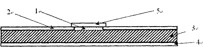
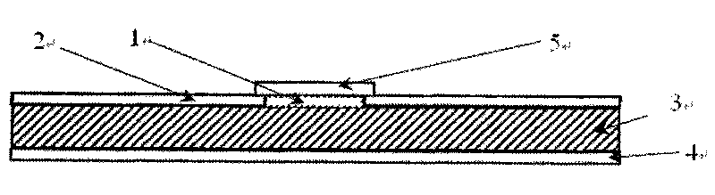
[0013] Below in conjunction with accompanying drawing, the present invention will be further described

[0014] Such as figure 1 As shown, the substrate of the microstrip circuit, that is, the dielectric substrate 3 is made of silicon material, and the grounded copper film 4 is placed under the dielectric substrate 3. The microstrip transmission line 2 is a copper strip with a thickness of 0.1 mm and a width of 2 mm. The gap between the microstrip transmission lines is 1 The width is 5mm. Plasma generator 5 is placed on the microstrip gap 1, it is made up of two copper electrodes with a thickness of 1.5mm and a width of 7mm, the electrode spacing is 4mm, and the electrodes are connected with the control power supply by wires; except for the opposite surfaces of the two copper electrodes, The rest of the surface is covered with insulating glue, and the lower end of the electrode is fixed on the dielectric substrate 3 with insulating glue, so that the discharge occurs in a limi...


PUM


Abstract

The invention relates to a plasma microstrip switch comprising a microstrip transmission line and a plasma generator, wherein the plasma generator clings to a microstrip substrate on a microstrip gap for blocking off an electromagnetic wave and generates a plasma layer with high density distributed along the surface of the substrate so as to completely cover the microstrip gap; and the conductor property of the plasma ensures that the electromagnetic wave which has the frequency lower than that of the plasma and is blocked off by the gap can be transmitted by the gap. A control power source system provides high voltage or zero potential for a discharge electrode of the plasma generator to control the generation and the attenuation of a discharge plasma, thereby controlling the conduction and the disconnection of the microstrip electromagnetic wave and achieving the switching function. The time for the generation and the attenuation of the discharge plasma is preferably in a microsecond, so that the requirement of the high-speed microstrip switch can be met. The invention has the advantages of wide working frequency band, high isolation degree, small insertion loss, high speed and good power property; meanwhile, the plasma microstrip switch has simple structure, feasible process and no mechanical part and can realize complete circuit control.

Description

technical field [0001] The invention relates to a microstrip switch, in particular to a plasma microstrip switch, and belongs to the technical field of microwave circuits. Background technique [0002] Microstrip line is one of the basic devices for microwave transmission and has been widely used in microwave circuits. The microstrip line can be printed on a very thin dielectric substrate, and its cross-sectional size is much smaller than that of the waveguide and the coaxial line, so that the wavelength of the electromagnetic wave on the transmission line is several times smaller than the wavelength of the free space, which better solves the problem of small For the optimization problem, microstrip circuits can be used to transmit electromagnetic signals in a smaller scale. The microstrip switch is the basic component for controlling the transmission of electromagnetic waves in the microstrip, and is used to control the on-off of the circuit, such as solid-state switches s...

Claims


Application Information

Patent Timeline
IPC IPC(8): H01P1/10H01P1/14
Inventor 欧阳吉庭缪劲松彭祖林曹菁蔡崧
Owner BEIJING INSTITUTE OF TECHNOLOGYGY
Why Eureka
Try Eureka