
Method for processing oil grooves in inner bores of copper bearing bush

A bearing bushing and copper processing technology, which is applied to metal processing equipment, metal processing machinery parts, supports, etc., can solve the problems of large cutting force, unsuitable for mass production requirements, high surface roughness, etc., and meet the requirements of mass production and high Effects on process quality and productivity

Active Publication Date: 2010-05-26
FAW GROUP
View PDF0 Cites 18 Cited by
  • Summary
  • Abstract
  • Description
  • Claims
  • Application Information

AI Technical Summary

Problems solved by technology

For small factories that do not have machine tools such as CNC machining centers, the traditional method is to use pointed-shaped forming tools to forcefully broach the oil groove on ordinary lathes. During processing, the copper bearing bushing is clamped on the three-jaw chuck of the lathe head. The main shaft is locked and does not rotate (that is, the workpiece does not rotate), and the pointed knife is driven to broach the required oil groove through the longitudinal feed of the large carriage. However, the problem with this method is that the cutting force is large, and it takes several knives to process an oil groove. , low efficiency, and high surface roughness, not suitable for mass production requirements

Method used


Image

  • Method for processing oil grooves in inner bores of copper bearing bush
  • Method for processing oil grooves in inner bores of copper bearing bush
  • Method for processing oil grooves in inner bores of copper bearing bush

Examples


Embodiment Construction

[0021] Below the present invention will be further described in conjunction with the embodiment in the accompanying drawing:

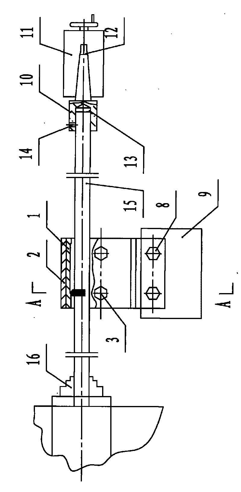
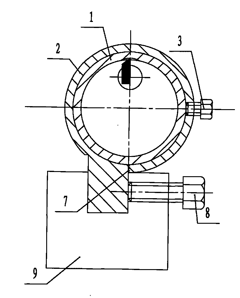
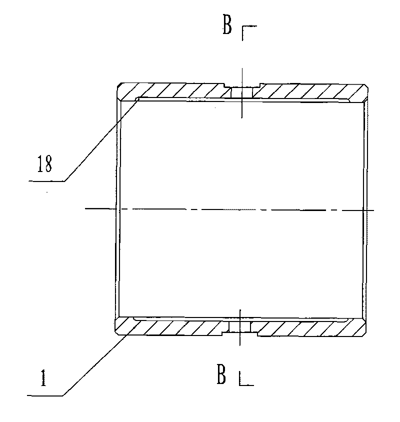
[0022] Figure 1 to Figure 8 Shown: 1. Copper bearing bushing, 2. Clamp body, 3. Set screw, 4. Ring body, 5. Fixing body, 6. Fastening workpiece screw hole, 7. 180° positioning marking line, 8. Fastening fixture screw, 9, lathe tool holder, 10, auxiliary positioning support tool, 11, lathe tailstock, 12, Morse taper hole, 13, tool bar hole, 14, lubricating oil hole, 15, tool bar, 16, Three-jaw chuck, 17, blade, 18, the first oil groove.

[0023] A method for processing the oil groove in the inner hole of the copper bearing bush of the present invention adopts the following process steps:

[0024] (1) First put the copper bearing bush 1 into the clamp body 2, and after the end faces are aligned, lock it with two set screws 3. The clamp body 2 is an integral structure, see Figure 7 , Figure 8 As shown, the clamp body 2 includes a ring body 4 and a ...


PUM


Abstract

The invention relates to method for processing oil grooves in inner bores of a copper bearing bush through a common lathe, which comprises the following steps: (1) fixing the copper bearing bush in a fixture body, and fixing the fixture body on a tool rest of the lathe; (2) inserting one end of an auxiliary positioning support tool into a Morse taper hole of a tail rack sleeve of the lathe, and processing a cutter arbor hole at the other end thereof; (3) passing a cutter arbor fixed with a blade through the copper bearing bush, clamping one end thereof on a lathe head, and extending the other end thereof into the cutter arbor hole; (4) starting the lathe to rotate the cutter arbor, moving the tool rest of the lathe, setting the starting position and depth of an oil groove, and flexibly processing the oil groove in the length; and (5) after the first oil groove is finished, retreating a tool bit, stopping the lathe, loosening a fastening piece, rotating the copper bearing bush 180 degrees in the fixture body, fixing the copper bearing bush, and repeating the step (4) to process the second oil groove. The method can be used for processing the oil grooves in the inner bores of the copper bearing bush through the lathe, the cutting force is small, high processing quality and production efficiency can be realized, and a requirement of mass production is met.

Description

technical field [0001] The invention relates to a method for processing an oil groove in the inner hole of a copper bearing bush with a common lathe, in particular to a method for processing the oil groove in the inner hole of the copper bearing bush with a tool and a fixture on a common lathe. Background technique [0002] There is a copper bearing bush on the machine such as image 3 , Figure 4 As shown, there are two oil grooves on the wall of the inner hole. For small factories that do not have machine tools such as CNC machining centers, the traditional method is to use pointed-shaped forming tools to forcefully broach the oil groove on ordinary lathes. During processing, the copper bearing bushing is clamped on the three-jaw chuck of the lathe head. The main shaft is locked and does not rotate (that is, the workpiece does not rotate), and the pointed knife is driven to broach the required oil groove through the longitudinal feed of the large carriage. However, the pr...

Claims


Application Information

Patent Timeline
IPC IPC(8): B23B41/00B23Q3/06B23Q3/18B23Q3/02
Inventor 黄建松
Owner FAW GROUP
Learn More