Method and device of integral type hollow fibrous membrane bioreactor based on fluid mechanics
A fluid mechanics and biological treatment technology, applied in the direction of sustainable biological treatment, biological water/sewage treatment, chemical instruments and methods, etc., can solve the problems of enhanced shearing effect, deterioration of suction effect, excessive strength, etc., and achieve staggered shearing Reduced power consumption, improved suction characteristics, and enhanced shear action
- Summary
- Abstract
- Description
- Claims
- Application Information
AI Technical Summary
Problems solved by technology
Method used
Image
Examples
Embodiment 1
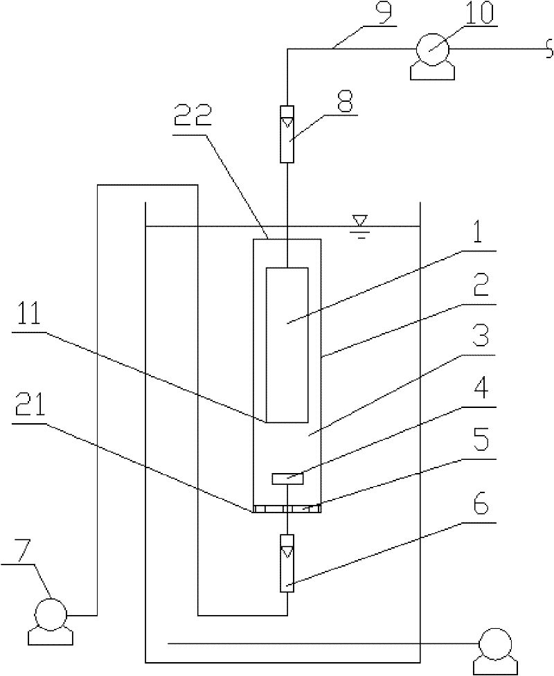
[0035] An integrated hollow fiber membrane biological treatment method based on hydrodynamics, comprising the following steps: setting the aeration head 4 directly under the membrane module 1, and then installing a flow inducing device 2 on the outside of the membrane module 1 and the aeration head 4, the flow inducing The device 2 isolates the sewage around the membrane module 1 and the aeration head 4 from the reaction tank to form a flow induction channel 3 that penetrates up and down, and the suction effect of the vacuum pump 10 is correspondingly isolated in the flow induction channel 3; the flow induction device 2 A rectification plate 5 is arranged at the lower end, and the rectification plate 5 will reduce the sludge being sucked into the flow induction channel 3 and directly contacted with the membrane module 1 .
[0036] An integrated hollow fiber membrane bioreactor device based on fluid mechanics, including a membrane module 1 and an aeration head 4, the aeration he...
Embodiment 2
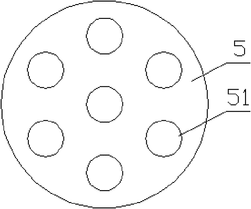
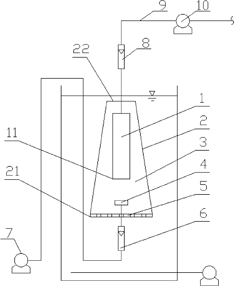
[0040] An integrated hollow fiber membrane bioreactor device based on fluid mechanics, including a membrane module 1 and an aeration head 4, the aeration head 4 is arranged directly below the membrane module 1, and the membrane module 1 and the aeration head 4 are equipped with a flow induction The device 2, the flow inducing device 2, the membrane module 1 and the aeration head 4 form a flow inducing channel 3 through up and down. The lower end of the flow inducing device 2 is provided with a rectifying plate 5, and the rectifying plate 5 is provided with a filter hole 51. The filter holes 51 on the rectifying plate 5 are distributed in an annular shape. The flow induction device 2 is in the shape of a truncated cone, and the opening at the lower end 21 of the flow induction device is larger than the opening at the upper end 22 of the flow induction device. The vertical distance between the lower end 11 of the membrane module and the lower end 21 of the flow inducing device i...
Embodiment 3
[0042] An integrated hollow fiber membrane bioreactor device based on fluid mechanics, including a membrane module 1 and an aeration head 4, the aeration head 4 is arranged directly below the membrane module 1, and the membrane module 1 and the aeration head 4 are equipped with a flow induction The device 2, the flow inducing device 2, the membrane module 1 and the aeration head 4 form a flow inducing channel 3 through up and down. The lower end of the flow inducing device 2 is provided with a rectifying plate 5, and the rectifying plate 5 is provided with a filter hole 51. The filter holes 51 on the rectifying plate 5 are distributed in an annular shape. The flow inducing device 2 is prismatic. The vertical distance between the lower end 11 of the membrane module and the lower end 21 of the flow inducing device is 30 cm. The opening diameter of the lower end 21 of the flow inducing device is 70 cm. A membrane water outlet flowmeter 8 is connected to the water outlet pipelin...
PUM
 Abstract
Description
Claims
Application Information
 - R&D
- Intellectual Property
- Life Sciences
- Materials
- Tech Scout
- Unparalleled Data Quality
- Higher Quality Content
- 60% Fewer Hallucinations
Browse by: Latest US Patents, China's latest patents, Technical Efficacy Thesaurus, Application Domain, Technology Topic, Popular Technical Reports.
© 2025 PatSnap. All rights reserved.Legal|Privacy policy|Modern Slavery Act Transparency Statement|Sitemap|About US| Contact US: help@patsnap.com


