Preparation method of copper foil antenna

A copper foil and antenna technology, applied in the field of copper foil antenna preparation, can solve the problems of high product rejection rate, unstable working pressure, short tool life, etc., and achieve the effect of comprehensive cost performance

Active Publication Date: 2010-05-26
东莞澳普林特精密电子有限公司
View PDF0 Cites 4 Cited by
  • Summary
  • Abstract
  • Description
  • Claims
  • Application Information

AI Technical Summary

Problems solved by technology

However, the die-cutting needs to be reciprocated, and the efficiency is low; the die-cutting contact surface is large, the working pressure is unstable, the product forming stability is not good, and the product scrap rate is relatively high; the tool life is short
Most flat knives cannot be repaired and used repeatedly. Once damaged, they can only be scrapped, so the overall life is relatively short.

Method used


Image

  • Preparation method of copper foil antenna
  • Preparation method of copper foil antenna
  • Preparation method of copper foil antenna

Examples


Embodiment Construction

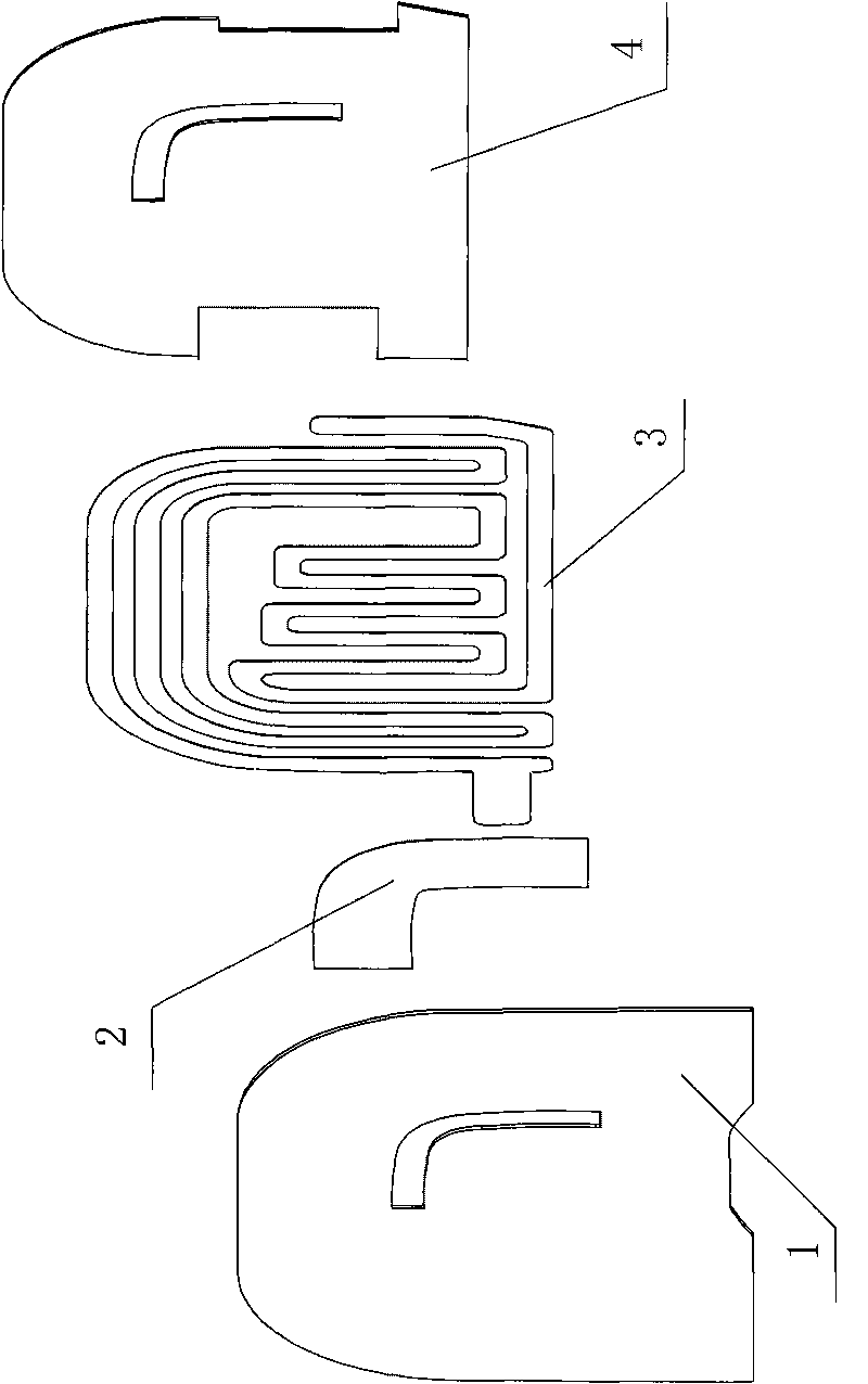
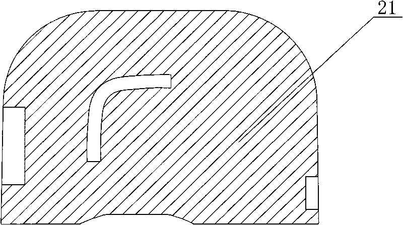
[0072] refer to figure 1 As shown, the method of the embodiment of the present invention is mainly to provide copper foil antennas for users (manufacturers of mobile phones, or customers using copper foil antennas, etc.). For the convenience of packaging, storage and transportation, the structural design of the products produced by the present invention is Four layers: black PC layer 21, mesh layer 22, copper foil layer 23 and transparent PET layer 24 in sequence.

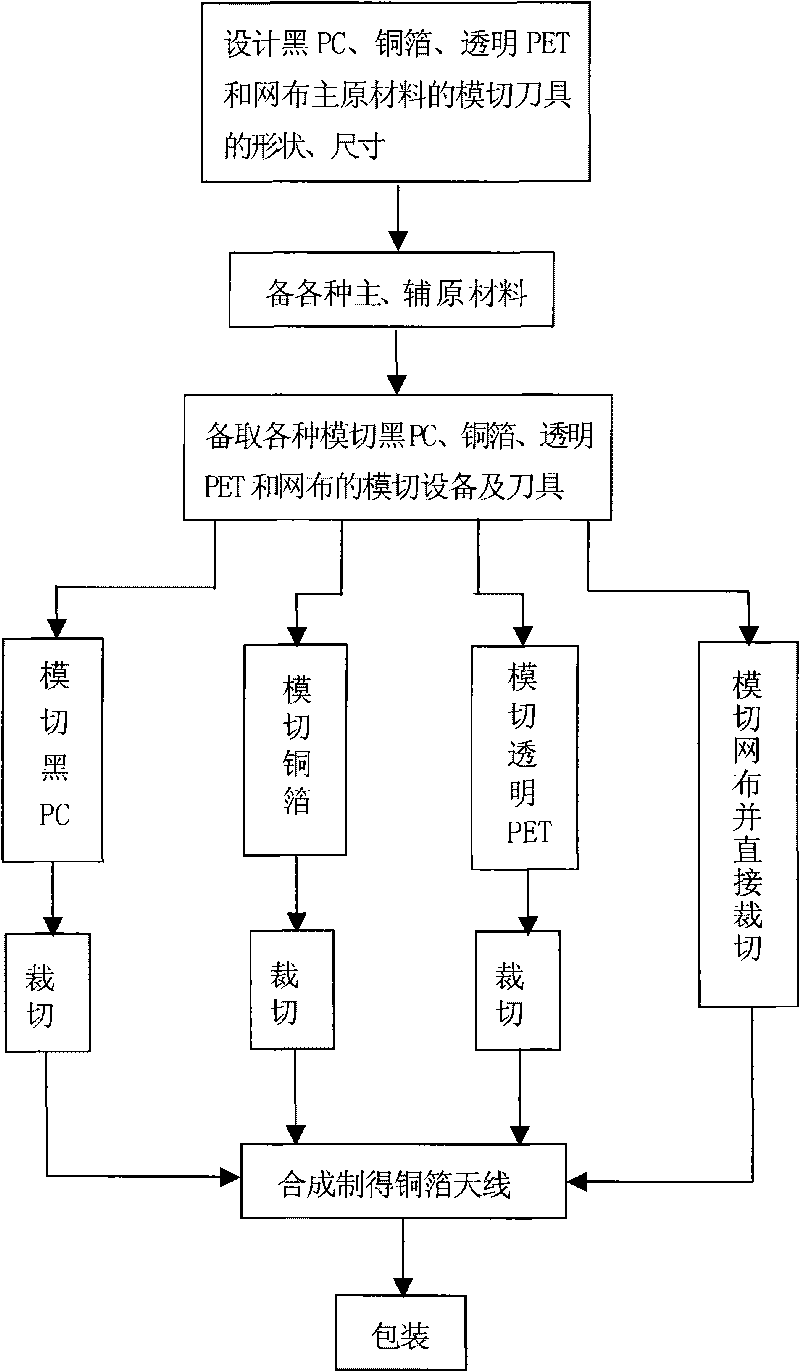
[0073] refer to figure 2 Shown, the die-cutting method of die-cut copper foil antenna of the present invention is:

[0074] 1. Basic design:

[0075] Design the shape and size of the die-cutting tool for the main raw materials of black PC, copper foil, transparent PET and mesh according to the requirements of the die-cut copper foil antenna;

[0076] Second, prepare raw materials:

[0077] Firstly prepare double-sided adhesive tape, PET, copper foil, black PC, transparent PET, mesh cloth, protective film and w...


PUM


Abstract

The invention relates to a preparation method of copper foil antenna and comprises the following steps: first, designing the shapes and dimensions of die cutting tools of materials according to requirements; preparing raw materials of double faced adhesive tape, PET, copper foil, PC, transparent PET protective film and exhausting film, respectively preparing tools for die cutting PC, copper foil,transparent PET and main material mesh cloth and installing on the tool seats corresponding to the used die cutting devices, respectively laminating and die cutting the raw material of PC, copper foil, transparent PET and mesh cloth to obtain a tape coiling group winded with initially shaped half-finished products of PC, copper foil and transparent PET and directly obtain the monomer half-finished product of mesh cloth; then placing the tape coiling group of the half-finished products of PC, copper foil and transparent PET on slicing machines to slicing; sticking PC, copper foil and transparent PET sequentially on fixed position on a jointed board to obtain the finally finished product of copper foil antenna. The method can replace the conventional methods to manufacture antennae, can satisfy the requirement on internally installed antennae in mobile phones well, can realize mass production, and opens up a new field for preparation technology of antennae.

Description

technical field [0001] The invention relates to a preparation method of a copper foil antenna. Background technique [0002] Traditional antennas generally use etched antennas or printed antennas, and the production of such antennas requires screen printing equipment and etching equipment. The production process will cause great pollution to the environment. And due to the limitation of its process method, it needs to invest a lot of manpower and equipment resources for mass production, and it is also difficult to manufacture antennas that meet high performance (such as built-in antennas for mobile phones), and the scrap rate is high, and the production efficiency is low. [0003] To solve this problem, it is necessary to develop a new type of antenna. Therefore, researchers have begun to devote themselves to the development of a new type of copper foil antenna. [0004] High-performance conductive copper foil has excellent adhesiveness, moisture resistance, corrosion resi...

Claims


Application Information

Patent Timeline
IPC IPC(8): H01Q1/38
Inventor 王俊茹
Owner 东莞澳普林特精密电子有限公司
Why Eureka
Try Eureka