

Composite reinforcing method for combining soft foundation light well point pipe with plastic drainage plate
A technology of plastic drainage boards and light well points, which is applied in infrastructure engineering, soil protection, construction, etc. It can solve the problems of muddy sites, spring soil, and the inability to reduce the water content of the silt interlayer soil, and achieve the water content of the soil. The effect of balance, short construction period, and cost-effective improvement
- Summary
- Abstract
- Description
- Claims
- Application Information
AI Technical Summary
Problems solved by technology
Method used
Image

Examples
Embodiment Construction
[0032] The specific process steps of this construction method are as follows (dynamic consolidation takes dynamic compaction as an example):
[0033] Step 1. Excavate the drainage ditch
[0034] For a large area of soft ground, if the light well plastic drainage well point precipitation reinforcement technology is adopted, several small areas can be set up in the area to be reinforced. Generally, one small area is 5000-10000m 2 . Open ditches shall be excavated between residential quarters, and the open ditches of the residential quarters shall connect with each other to form a drainage network. A certain number of water collection wells shall be set at the junctions of open ditches, and the open ditch water shall be discharged into adjacent rivers by self-flow or forced drainage.
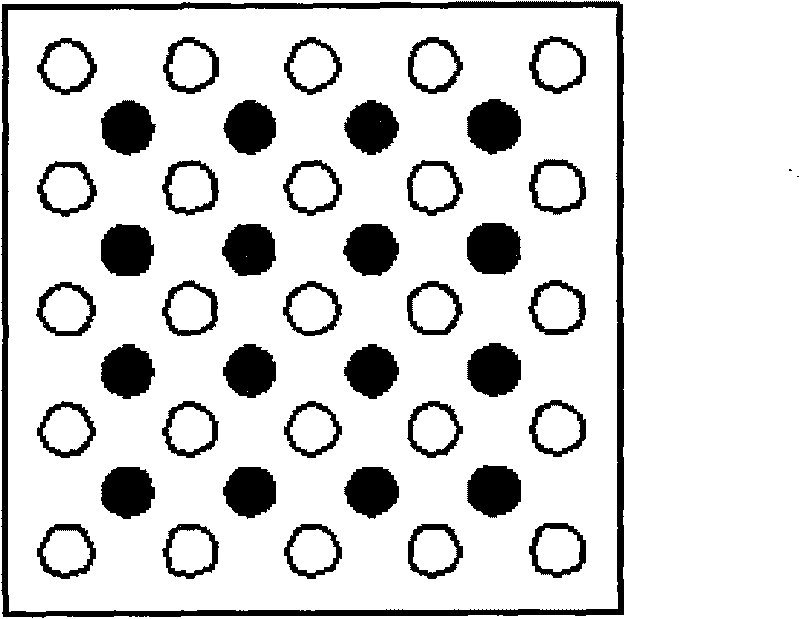
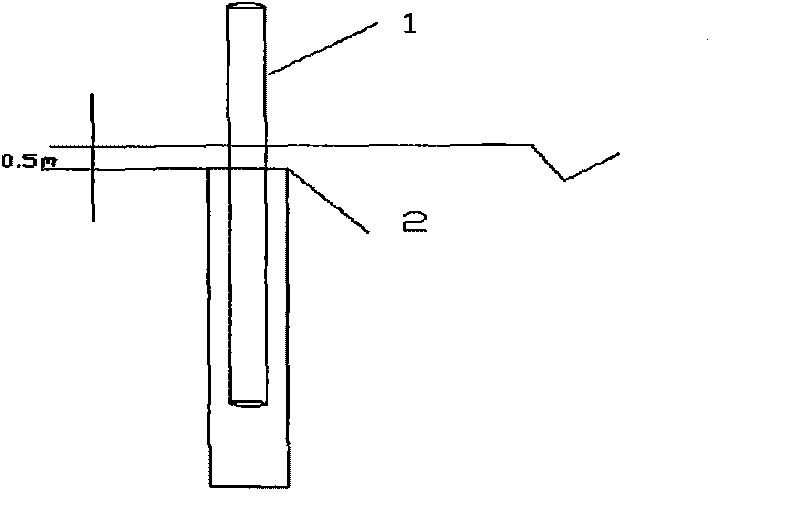
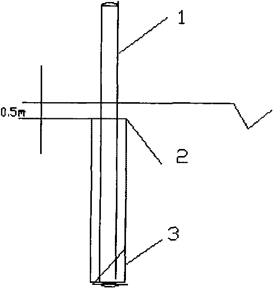
[0035] Step 2. Arrange the composite well point formed by the light well point pipe combined with the plastic drainage plate (referred to as the light well plastic drainage well point) and carry...
PUM
 Abstract
Description
Claims
Application Information