
Electron beam evaporation plant

A technology of electron beam evaporation and copper crucible, which is applied in the direction of vacuum evaporation plating, ion implantation plating, metal material coating technology, etc., can solve problems such as aluminum splashing accidents, achieve small heat conduction losses, avoid aluminum splashing accidents, and melt uniform effect

Inactive Publication Date: 2010-06-23
ZHUZHOU CSR TIMES ELECTRIC CO LTD
View PDF0 Cites 3 Cited by
  • Summary
  • Abstract
  • Description
  • Claims
  • Application Information

AI Technical Summary

Problems solved by technology

However, due to the good heat dissipation effect of the copper crucible, when the aluminum source in the copper crucible is evaporated by using cooling water to cool down, only the aluminum layer is in a melting state at the position scanned by the electron beam, while the aluminum source at other positions close to the copper crucible wall is not. Melting, so in order to maintain the evaporation rate of 40A / S, the current of the electron gun must be added to 0.8A to achieve
At the same time, due to the uneven melting of the aluminum source, when the electron beam scans on the unmelted aluminum source, it is easy to cause aluminum splashing accidents

Method used


Image

  • Electron beam evaporation plant
  • Electron beam evaporation plant
  • Electron beam evaporation plant

Examples


Embodiment Construction

[0026] The present invention will be described in detail below in conjunction with the accompanying drawings and specific embodiments.

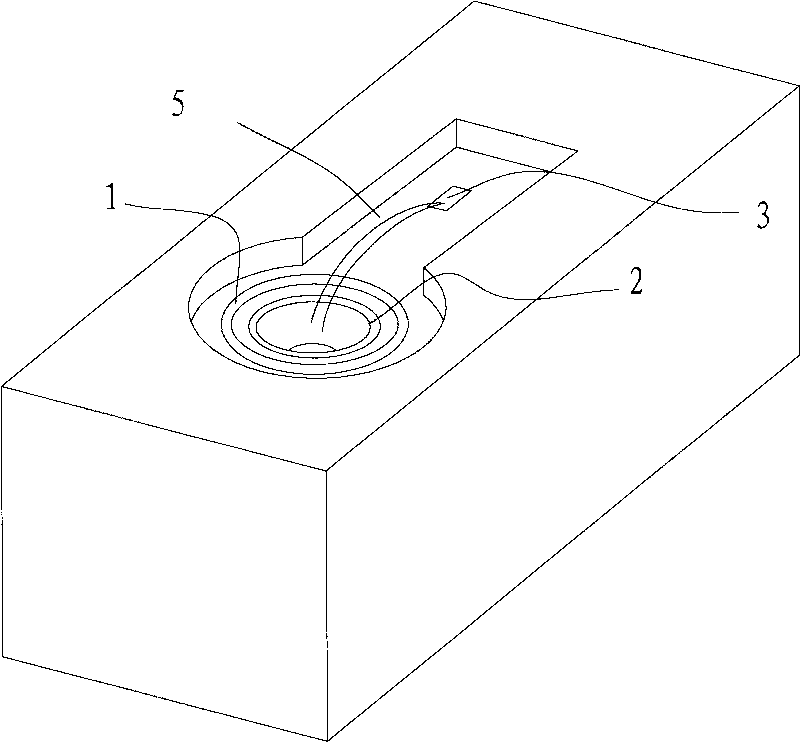
[0027] figure 1 It is a schematic structural diagram of the electron beam evaporation device of the present invention.

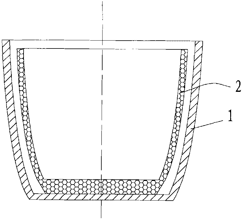
[0028] Such as figure 1 As shown, the electron beam evaporation device of the present invention includes a copper crucible 1, an electron gun, a cooling water pipe, a magnet, a deflection coil (not shown) and the like. The electron gun is used to emit an electron beam that heats the aluminum source to evaporate the aluminum source. The electron gun is arranged in the evaporation device and emits the electron beam 5 to the crucible through the electron beam outlet 3. The magnet and the deflection coil are used to control the direction and deflection of the electron beam 5 angle, and the cooling water pipe is used for cooling the magnet and deflection coil.

[0029] A crucible lining 2 made of heat-resistant material is ar...


PUM

PropertyMeasurementUnit
melting pointaaaaaaaaaa

Abstract

The invention discloses an electron beam evaporation plant, comprising a copper crucible with crucible lining made from heat resisting materials inside. Clearance is left between the crucible lining and the copper crucible, which greatly reduces the thermal coefficient between the crucible lining and the copper crucible so as to effectively avoid the negative influences on the emission of electron beams when heat of the crucible lining is conducted to the magnet and coil through the copper crucible. Meanwhile, due to small heat conduction loss, a relatively smaller beam power can be employed to maintain a relatively high evaporation rate. As the aluminum source melting in the crucible lining is even, aluminum splashing can be effectively avoided.

Description

technical field [0001] The invention relates to a chip evaporation aluminum plating technology, in particular to an electron beam evaporation device using an electron beam evaporation aluminum source. Background technique [0002] In order to lead out the electrodes of power semiconductor devices, it is usually realized by evaporating the aluminum source and forming an aluminum layer on the surface of the chip. [0003] At present, the evaporation of aluminum sources is mostly carried out by electron beam evaporators. When using electron beam evaporators to evaporate aluminum sources, we usually use oxygen-free copper crucibles, that is, place copper crucibles in the middle of electron beam evaporators, and put aluminum in the copper crucibles. The aluminum source is irradiated with electron beams, and the aluminum source absorbs the energy of the electron beams to rapidly heat up, vaporize and evaporate, and generate a lot of heat. In the electron beam evaporator, in order...

Claims


Application Information

Patent Timeline
Patent Type & Authority Applications(China)
IPC IPC(8): C23C14/30
Inventor 王政英黄建伟邹冰艳潘昭海曹伟宸
Owner ZHUZHOU CSR TIMES ELECTRIC CO LTD
Learn More