Annular circular polarization ceramic antenna based on quadrature coupling feed

A ceramic antenna, orthogonal coupling technology, applied in the direction of loop antenna, electrical short antenna, antenna, etc., can solve the problems of inability to guarantee the coverage of mobile satellite communication, increase aerodynamic resistance, and insufficient beam width, etc., to facilitate processing and application, good antenna gain, effect of improved matching performance and radiation efficiency

Inactive Publication Date: 2010-06-23
SOUTH CHINA UNIV OF TECH
View PDF3 Cites 23 Cited by
  • Summary
  • Abstract
  • Description
  • Claims
  • Application Information

AI Technical Summary

Problems solved by technology

[0007] Traditional helical antennas are often used in satellite navigation systems to generate circularly polarized wave propagation, since the antenna needs to extend upwards from the surface of the grounded metal plate to a height of λ 0 / 4~λ 0 / 2 (where λ 0 for the antenna operating wavelength) a helix, so it's not well styled and adds aerodynamic drag
The low-profile microstrip antenna can make up for the above shortcomings, but the traditional single-feed microstrip circularly polarized antenna still has the following disadvantages: (1) There is not enough beam width to ensure a wide enough coverage for mobile satellite communications; (2) When there is enough beam width, the impedance bandwidth is not enough
Although the radiation beam width of the microstrip antenna is reduced by using a dielectric material with a high dielectric constant or using microstrip slotting technology to produce a wide radiation beam, this method reduces the impedance bandwidth and cannot meet the requirements.

Method used


Image

  • Annular circular polarization ceramic antenna based on quadrature coupling feed
  • Annular circular polarization ceramic antenna based on quadrature coupling feed
  • Annular circular polarization ceramic antenna based on quadrature coupling feed

Examples


Embodiment Construction

[0034] The implementation of the present invention will be described in detail below in conjunction with the accompanying drawings, but the scope of protection required by the present invention is not limited to the following embodiments.

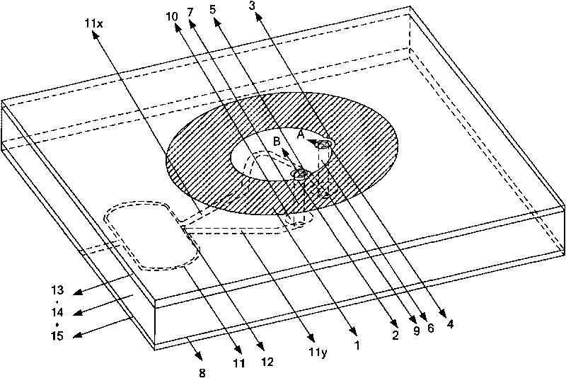
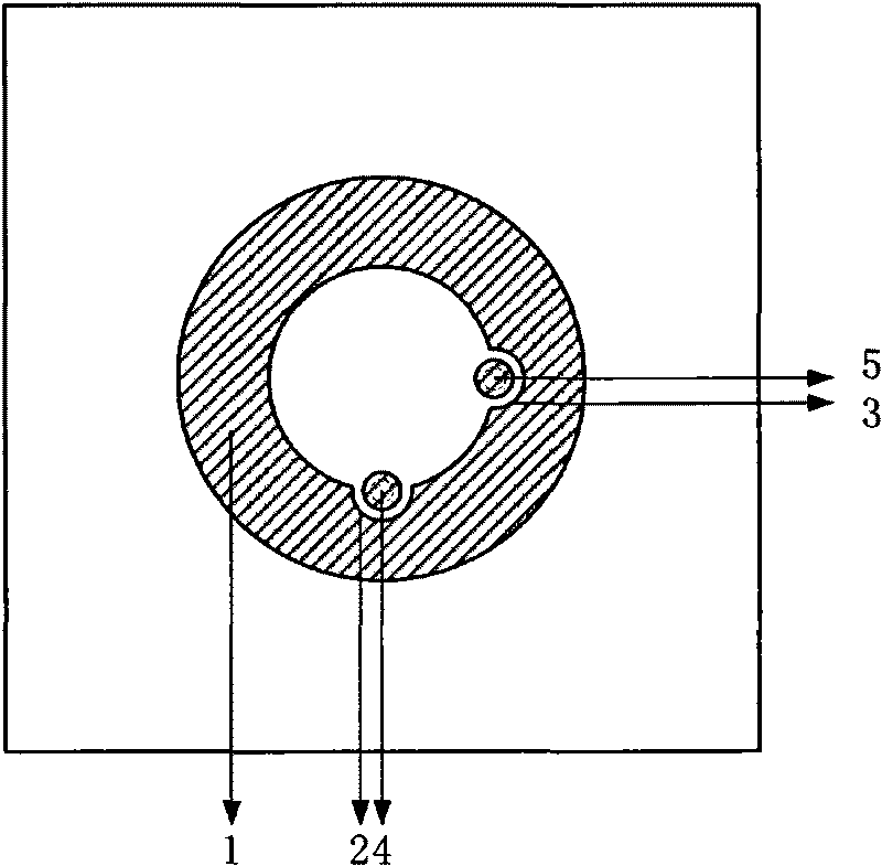
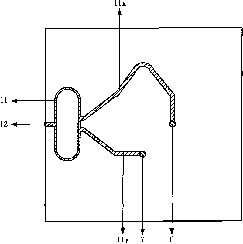
[0035] Such as figure 1 , 2a , 2b, the circular circularly polarized ceramic antenna based on orthogonal coupling feed is implemented in the form of a microstrip circuit, including an upper microstrip antenna structure, an upper dielectric substrate 13, a middle dielectric substrate 14, a metal floor layer 8, The lower dielectric substrate 15 and the lower Wilkinson power divider. The upper dielectric substrate 13 and the middle dielectric substrate 14 are stacked together to form a dielectric composite substrate of an annular metal radiator. The upper microstrip antenna structure and the metal floor layer 8 are respectively attached to the upper and lower sides of the dielectric composite substrate; The substrate 15 is connected, and the...


PUM


Abstract

The invention discloses an annular circular polarization ceramic antenna based on quadrature coupling feed, which comprises an upper layer microstrip antenna structure, an upper medium substrate, a middle layer medium substrate, a metal floor layer, a lower layer medium substrate and a bottom layer Wilkinson power divider; the upper layer microstrip antenna structure includes an annular antenna and two metal circular sheets which are small circular sheets respectively taking two points as circle centers, and are respectively positioned at the area of two arcs and inner circle; the bottom layer Wilkinson power divider is composed of a high impedance wire, a first low impedance wire, a second low impedance wire and a SMD resistor; the feature impedance of the high impedance wire is times ofthe feature impedance z0 of the first low impedance wire and the second low impedance wire; the upper layer medium substrate, the middle layer medium substrate and the lower layer medium substrate are all ceramic medium. The antenna feed mechanism adopts two circular metal sheets to generate two quadrature current sources with the same amplitude and also can extend the axial ratio bandwidth of the annular metal antenna to increase the adjusting degree of freedom of the antenna.

Description

technical field [0001] The invention relates to a satellite navigation and positioning antenna, which can work simultaneously in the B1 frequency band (1561.098MHz) and B1-2 frequency band (1589.742MHz) of China's Beidou second-generation system, and the L1 frequency band (1575.42MHz) of the American GPS system and Compatible receiving antenna for multiple navigation systems in the L1 frequency band (1602.56-1615.50MHz) of European GLONASS. Background technique [0002] The satellite navigation industry is a national strategic high-tech industry. It is a typical technology-intensive and service-oriented IT industry. Its development prospects are very broad. It has become one of the eight major wireless industries in the world. The rapid information industry has become another new growth point of the third IT economy. The satellite and positioning GPS application industry represented by the US Global Positioning System GPS has gradually become a global high-tech industry. m...

Claims


Application Information

Patent Timeline
Patent Type & Authority Applications(China)
IPC IPC(8): H01Q13/08H01Q1/38H01Q1/14H01Q1/48H01Q7/00H01Q5/00H01P5/12H01Q5/307
CPCH01Q9/0435H01Q9/0457H01Q9/0464
Inventor 胡斌杰张洪林王晓欣
Owner SOUTH CHINA UNIV OF TECH
Why Eureka
Try Eureka