Reclamation treatment method of oil field tank bottom oil sludge

A treatment method and sludge technology, applied in the pyrolysis treatment of sludge, by-product vaporization, etc., can solve the problems of oily sludge property fluctuation, large mass transfer performance, poor treatment effect, unstable operation, etc. quality, improving mass transfer performance, and avoiding operational failures

Inactive Publication Date: 2010-06-30
TSINGHUA UNIV
View PDF0 Cites 28 Cited by
  • Summary
  • Abstract
  • Description
  • Claims
  • Application Information

AI Technical Summary

Problems solved by technology

[0005] Aiming at the problem that the current oilfield tank bottom sludge treatment process is unstable due to the large fluctuation of sludge properties and poor mass transfer performance, the treatment effect is not good, the oil recovery rate

Method used


Image

  • Reclamation treatment method of oil field tank bottom oil sludge
  • Reclamation treatment method of oil field tank bottom oil sludge

Examples


Embodiment 1

[0041] The ratio of oily sludge, sand, oil and water in an oilfield tank bottom is 68.27:22.71:9.21.

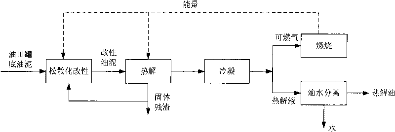
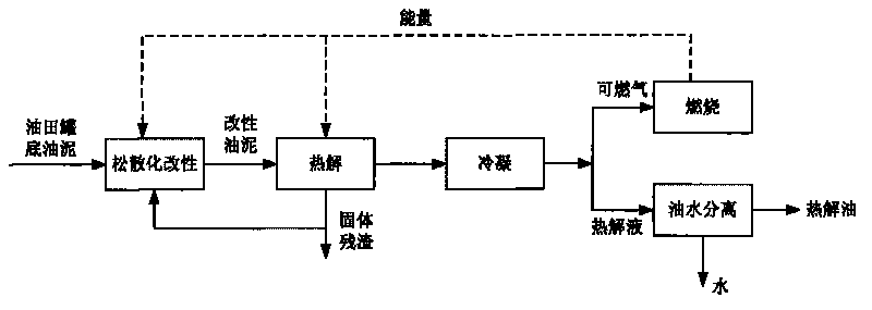
[0042] Heat the oilfield tank bottom sludge to 150°C, add 5% solid residue with a particle size of less than 1mm, and carry out loosening and modification in a twin-shaft mixer; the modified sludge enters a paddle-type pyrolysis furnace and heats up at 500°C The reaction time is 45 minutes, and the solid residue is discharged from the furnace; the condensed liquid obtained by the condensation of the precipitated gas is added with concentrated sulfuric acid as a demulsifier, and the pyrolysis oil is separated; the combustible gas is burned to provide heat for the system. As a result of the reaction, 0.13 tons of pyrolysis oil, 0.07 tons of combustible gas and 0.80 tons of solid residue can be produced for every ton of oilfield tank bottom sludge treated. The treatment reduction rate reaches 20%. From the perspective of oil conversion in sludge, 57% of the oil is converted int...

Embodiment 2

[0044] The mass ratio of the oilfield tank bottom sludge, sand, oil and water components in an oilfield is: 54.26:39.12:6.62.

[0045] Heat the oilfield tank bottom sludge to 150°C, add 5% solid residue with a particle size of less than 1mm, and carry out loosening and modification in a twin-shaft mixer; the modified sludge enters a paddle-type pyrolysis furnace and heats up at 550°C The reaction time is 30 minutes, and the solid residue is discharged from the furnace; the condensed liquid obtained by the condensation of the precipitated gas is added with concentrated sulfuric acid as a demulsifier, and the pyrolysis oil is separated; the combustible gas is burned to provide heat for the system. As a result of the reaction, 0.25 tons of pyrolysis oil, 0.08 tons of combustible gas and 0.67 tons of solid residue can be produced for every ton of oilfield tank bottom sludge treated. The treatment reduction rate reached 33%. In terms of oil conversion in sludge, 64% of the oil is ...


PUM


Abstract

The invention discloses an oil sludge treatment method which comprises the following steps of: first, carrying out loose modification on oil field tank bottom oil sludge, then carrying out pyrolysis, and obtaining solid residue and gas product; condensing the gas product and obtaining pyrolysis liquid and combustible gas; and carrying out oil-water separation on the pyrolysis liquid, and obtaining pyrolysis oil. The reclamation treatment method of oil field tank bottom oil sludge can effectively recover oil resource in the oil sludge, realizes self-heat-supply of a system and high-efficiency recovery utilization of energy, and achieving the aim of harmless treatment of the oil sludge. Compared with other treatment technologies, the technology has the advantages of stable and reliable operation, high oil resource recovery rate, strong adaptability and low secondary pollution, thus being a reclamation treatment technology of oil field tank bottom oil sludge which is worth popularizing.

Description

technical field [0001] The invention belongs to the field of solid waste treatment, and in particular relates to a resource treatment method for oil sludge at the bottom of oilfield tanks. Background technique [0002] Oilfield tank bottom sludge refers to a type of oily sludge deposited at the bottom of various storage tanks (oil storage tanks, oil-water separation tanks) during oil extraction. As most oil fields in my country enter the "three high" (high water cut, high oil recovery rate, high recovery degree) oil recovery period and the adoption of tertiary oil recovery technology, the production of this kind of oil sludge continues to increase, and the annual output in my country exceeds 300,000 tons . In addition to sand and water, oilfield tank bottom sludge also contains more than 20% crude oil. The presence of this part of oil makes the sludge environmentally harmful and is classified as hazardous waste; it also makes the sludge have the potential for resource utiliz...

Claims


Application Information

Patent Timeline
IPC IPC(8): C02F11/10
CPCY02W10/40
Inventor 刘建国宋薇聂永丰
Owner TSINGHUA UNIV
Why Eureka
Try Eureka