Integrated engine braking device with mechanical chaining and method for changing movement of engine air valve

An engine braking and engine technology, applied in the direction of machine/engine, engine components, valve devices, etc., can solve the problems of unreliable braking system, asymmetric load of valve or valve bridge, too sensitive disturbance, etc., to avoid large compression and overload problems, reducing manufacturing tolerance requirements, eliminating the effects of non-following or collisions

Active Publication Date: 2010-07-07
SHANGHAI UNIVERSOON AUTOPARTS CO LTD
View PDF5 Cites 13 Cited by
  • Summary
  • Abstract
  • Description
  • Claims
  • Application Information

AI Technical Summary

Problems solved by technology

[0031] 1) The previous braking system could only be installed on one specific type of engine;
[0032] 2) The moment of inertia of the previous braking system was too large, and the reaction (on and off) time was too long;
[0033] 3) The previous braking system was driven by hydraulic pressure, which was too flexible, resulting in reduced engine braking performance and increased load;
[0034] 4) The previous braking system caused an asymmetric load on th

Method used


Image

  • Integrated engine braking device with mechanical chaining and method for changing movement of engine air valve
  • Integrated engine braking device with mechanical chaining and method for changing movement of engine air valve
  • Integrated engine braking device with mechanical chaining and method for changing movement of engine air valve

Examples


Embodiment 1

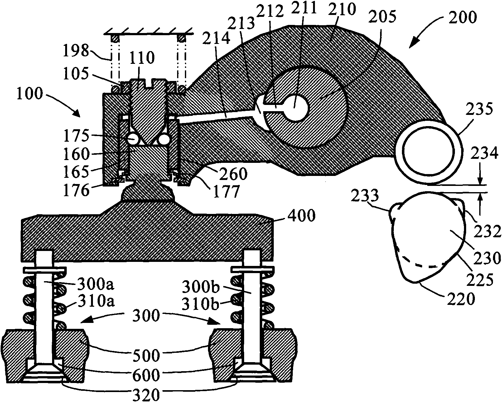
[0092] Figure 3A and 3B is a schematic view of the first engine brake embodiment of the present invention in its "OFF" and "ON" positions. The drive mechanism 100 is integrated in a rocker arm 210 of an engine exhaust valve train or valve actuator 200 . The exhaust valve train has many components, including cam 230 , cam follower 235 , rocker arm 210 , valve bridge 400 , and exhaust valve 300 . Exhaust valve 300 is biased against valve seat 320 of engine block 500 by engine valve spring 310 , preventing gas from flowing between the engine cylinder and exhaust pipe 600 . The rocker arm 210 is oscillatingly installed on the rocker shaft 205 , and transmits the movement of the cam 230 to the exhaust valve 300 to make it open and close periodically.

[0093] The exhaust valve system may also have other components, such as being connected to the brake piston 160 below 162 ( Figure 3B ) are like foot pads, which are omitted here for brevity. The cam 230 has a large boss 220 a...

Embodiment 2

[0100] Figure 5A and 5B yes Figure 3A and 3B In another embodiment of the illustrated engine brake device embodiment, an engine brake reset mechanism 150 is added on the basis of the drive mechanism 100 . The reset mechanism includes a reset piston 166 that slides within a reset hole 169 in the rocker arm 210 . When the engine is running normally, the reset piston 166 is biased by the spring 199 on the top of the reset hole 169 ( Figure 5A ), and the spring 199 is fixed on the rocker arm 210 by the screw 179 ( Figure 5B ). The design of the spacing 185 between the reset piston 166 and the cylinder makes the reset piston 166 reset without contacting the cylinder when the engine is running normally ( Figure 5A ).

[0101] With the reset mechanism 150, Figure 4A and 4B The brake control mechanism 50 shown does not require a three-way solenoid valve 51 . Since the reset mechanism is also an oil drain mechanism, draining oil from the brake actuation mechanism 100 ca...

Embodiment 3

[0112] Figure 8A and 8B It is another embodiment of the engine braking device of the present invention. The drive mechanism 100 employs a different ball locking mechanism. Roller ball 175 is controlled by three surfaces on three different parts of drive mechanism 100 . The first surface is a tapered surface on brake piston 160 . The second surface is the flat surface of the bottom of the slack adjustment screw 110 . The third surface is related to the position of the ball locking mechanism. When the ball locking mechanism is in the retracted position, the third surface is the small diameter cylinder of the ball locking piston 165 ( Figure 8A ); when the ball locking mechanism is in the extended position, the third surface is the large diameter cylindrical surface of the ball locking piston 165 ( Figure 8B ). Like the previous embodiments, the valve gap adjusting mechanism is integrated with the driving mechanism 100 . A gasket with a hole can be added between the sc...


PUM


Abstract

The invention discloses an integrated engine braking device (engine retarder) with mechanical chaining and a method for changing the movement of an engine air valve. A driving mechanism of the device is partially or completely integrated in one or more components of a vent valve train of the engine and can move between a non-operating position and an operating position. On the non-operating position, the driving mechanism retracts and is separated from the normal operation of the engine; and on the operating position, the driving mechanism extends out to form mechanical chaining, and the vent valve of the engine is opened to generate the operation of braking the engine. On the top of the valve lift curve, the resetting mechanism of the device leads the driving mechanism to retract from an extending position so that the valve lift curve can be reset to be small. The invention also provides a method for changing the movement of the engine air valve, comprising the steps of operating and resetting the braking device. The device adopts the mechanical chaining, has simple structure and reliable running, avoids the problem of great compression of hydraulic chaining and reduces the braking response time.

Description

technical field [0001] The present invention relates to internal combustion engine braking, in particular to an engine braking device (engine retarder) integrated in an engine valve train and a method for converting an internal combustion engine from normal operation to braking operation. Background technique [0002] It is well known to use an internal combustion engine as a means of braking, simply by temporarily converting the engine to a compressor. This conversion can be achieved by cutting off the fuel, opening the exhaust valve at or near the end of the engine piston compression stroke, allowing the compressed gas (air during braking) to be released, and the energy absorbed by the engine during the compression stroke. It cannot be returned to the engine piston during the subsequent expansion stroke, but is dissipated through the engine's exhaust and cooling system. The end result is efficient engine braking. [0003] Engine braking is necessary for internal combusti...

Claims


Application Information

Patent Timeline
IPC IPC(8): F01L13/06
Inventor 杨洲
Owner SHANGHAI UNIVERSOON AUTOPARTS CO LTD
Why Eureka
Try Eureka