Differential automatic test system for photocatalytic reaction

An automatic test system and photocatalytic reaction technology, which is applied in the field of catalytic chemical reaction test experimental system, can solve the problems of lack of reaction pressure control, etc., and achieve the effect of simple and clear system, easy and uniform distribution, and simple connection

Inactive Publication Date: 2010-07-07
XI AN JIAOTONG UNIV
View PDF0 Cites 7 Cited by
  • Summary
  • Abstract
  • Description
  • Claims
  • Application Information

AI Technical Summary

Problems solved by technology

[0008] At present, in the photocatalytic reaction process, there is a general lack of control over the reaction pressure, and the integral measurement method is usually used; after searching and searching various patents and literatures, it has been shown that there is no report on the differential automatic test of the reaction. There are no reports of similar devices

Method used


Image

  • Differential automatic test system for photocatalytic reaction
  • Differential automatic test system for photocatalytic reaction
  • Differential automatic test system for photocatalytic reaction

Examples


Embodiment Construction

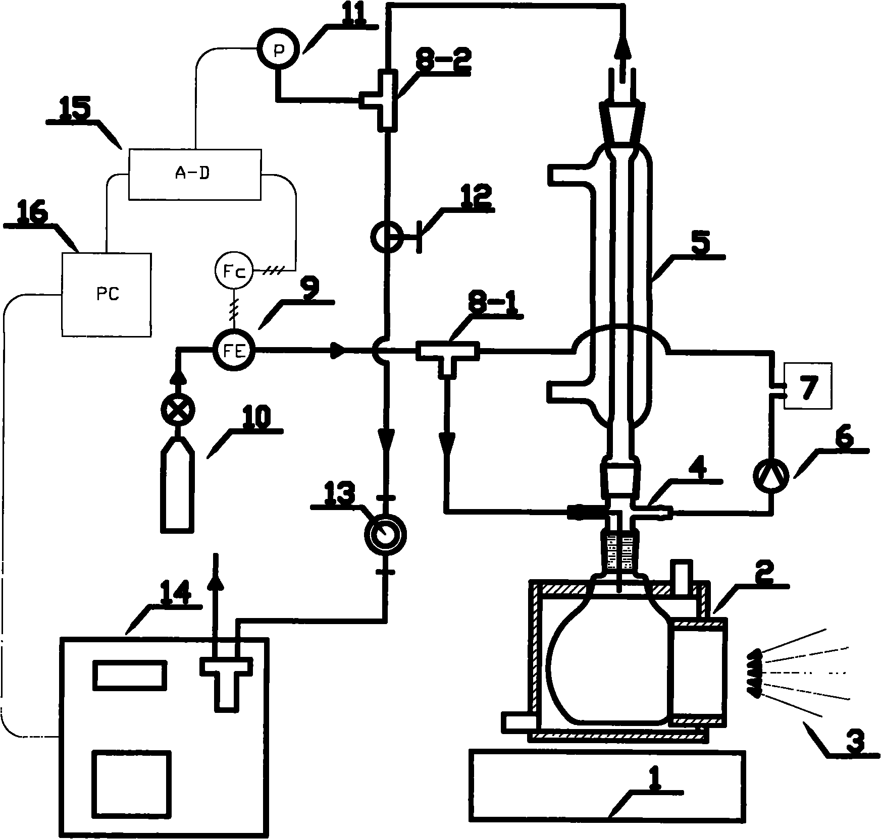
[0031] The content of the present invention will be described in further detail below in conjunction with the accompanying drawings.

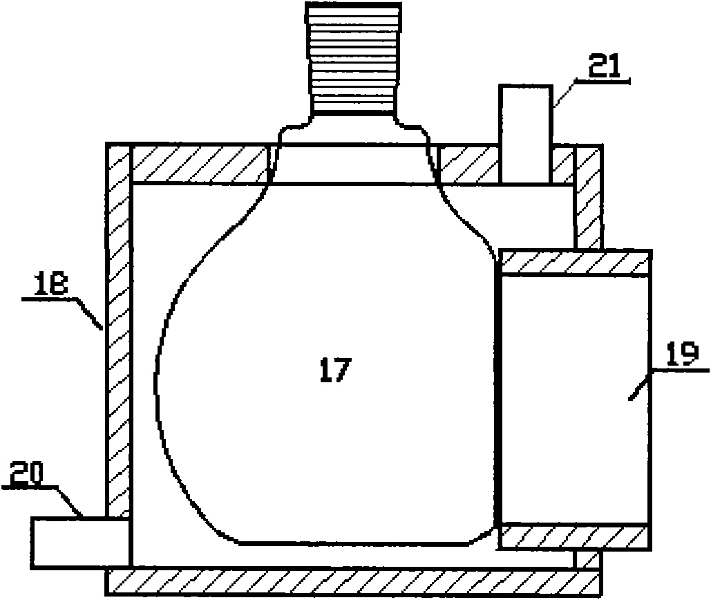
[0032] Such as figure 1 As shown, the photocatalytic reaction differential automatic test system: in this system, the magnetic stirrer 1 is located at the bottom of the photocatalytic reactor 2, and its right side is a xenon lamp point light source 3 (the horizontal side of the light path faces the photocatalytic reactor 2, from left to Right to the light-receiving surface), which is connected to the grinding port, which is used to connect the split air pipe 4. The split air pipe 4 has four ports, the upper and lower are grinding ports, and the left and right are branch pipes; the upper grinding port is connected to the condenser pipe 5; the left branch pipe is connected to the three-way valve 8-1, and the right branch pipe is the circulating gas outlet, which is connected to the circulating pump 6 through the pipeline and the continuous analy...


PUM


Abstract

The invention discloses a differential automatic test system for photocatalytic reaction, which comprises a reaction part, a circulation part, a pressure control part, a temperature control part and a measurement control part. The reaction part comprises a magnetic stirrer, a reactor, a xenon light source and the like; the circulation part comprises a gas circulation pump, a spherical glass condenser tube, a gas chromatography, a reactor, a pneumatic pipe and the like; the pressure control part comprises a gas mass flowmeter, a flow stabilizing valve, a digital pressure gauge, a vacuum pump and the like; the temperature control part comprises a constant-temperature circulation pump, a reactor temperature control jacket, a spherical glass condenser tube and the like; and the measurement control part comprises a continuous analyzer, a gas chromatography, a data acquisition board, a computer and the like. The system is used for photocatalytic hydrogen production test, and adopts carrier gas to bring out gas products in the reactor, thereby realizing the differential measurement. Moreover, the reaction temperature and the reaction pressure can be set, the instant hydrogen production rate in the photocatalytic reaction can be accurately and promptly obtained, and the system can be used in the test of photocatalytic reaction with involvement or production of other kinds of gases.

Description

technical field [0001] The invention belongs to a catalytic chemical reaction test experimental system, in particular to a photocatalytic reaction differential automatic test system. Background technique [0002] The basic principle of semiconductor photocatalytic reaction is: when a semiconductor photocatalyst is irradiated by sunlight (mainly visible light and ultraviolet light), the electrons inside it are excited to transition from the valence band to the conduction band, generating free electrons and holes. When electrons and holes migrate to the semiconductor surface, they interact with the adsorbed substances; for aqueous solutions, they can react to generate hydrogen or oxygen or both. The speed of photocatalytic reaction is affected by many factors such as catalyst, reaction solution, reactor, light source (spectrum and irradiance, etc.), reaction temperature and pressure, and some of these conditions are actively controlled to reflect the intrinsic characteristics ...

Claims


Application Information

Patent Timeline
Patent Type & Authority Applications(China)
IPC IPC(8): G01N30/02G01N30/28
Inventor 郭烈锦刘欢
Owner XI AN JIAOTONG UNIV
Why Eureka
Try Eureka