Device and method for shaping amorphous alloy thin-wall slim pipe

A technology of amorphous alloy and slender tubes, which is applied in the field of forming devices for slender amorphous alloy tubes, can solve the problems of thin walls that cannot be filled, and achieve the effect of simple device structure

Inactive Publication Date: 2010-07-14
HARBIN INST OF TECH
View PDF1 Cites 17 Cited by
  • Summary
  • Abstract
  • Description
  • Claims
  • Application Information

AI Technical Summary

Problems solved by technology

[0003] The purpose of the present invention is to solve the problem that existing methods for preparing amorphous alloy pipes mainly include copper mold casting, core pulling and induction suction casting, and copper mold casting and core pulling prepare thin-walled amorphous alloy pipes (wall thickness is less than 1mm). ), the thin-walled part cannot be filled; when the induction suction casting method is used to prepare alloys containing active metals, the induction crucible is likely to react with the amorphous alloy. A thin-walled elongated tube forming device for amorphous alloy is provided. and methods

Method used


Image

  • Device and method for shaping amorphous alloy thin-wall slim pipe
  • Device and method for shaping amorphous alloy thin-wall slim pipe
  • Device and method for shaping amorphous alloy thin-wall slim pipe

Examples


specific Embodiment approach 1

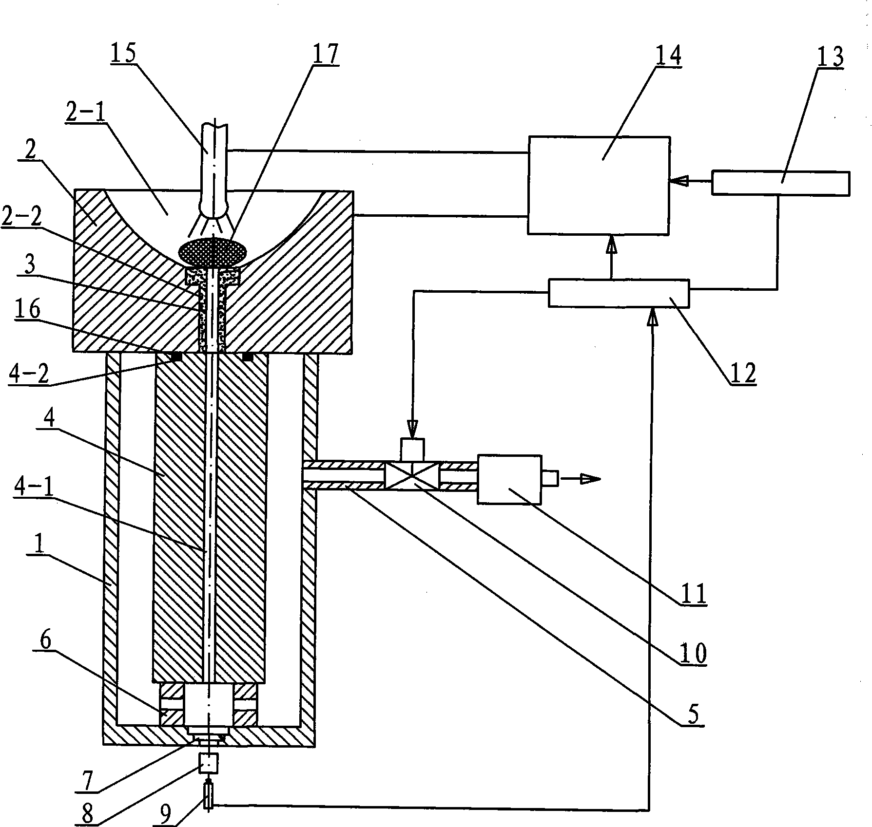
[0008] Specific implementation mode one: combine Figure 1 ~ Figure 3 Describe this embodiment, this embodiment includes an arc melting furnace 1, a copper crucible 2, a graphite tube 3, a connecting pipe 5, a support pad 6, a quartz glass 7, a temperature measuring device 8, an infrared sensor 9, a suction casting valve 10, and a mechanical pump 11 , tungsten rod 15, metal mold 4, suction casting controller 12 and melting current controller 13, one end of the connection pipe 5 is arranged on the side wall of the arc melting furnace 1, and the other end of the connection pipe 5 is connected with the mechanical pump 11, suction casting The valve 10 is installed on the connecting pipe 5, the quartz glass 7 is installed in the bottom center hole of the arc melting furnace 1, the temperature measuring device 8 is located below the bottom center hole of the arc melting furnace 1, and the infrared sensor 9 is located below the temperature measuring device 8, The upper end surface of...

specific Embodiment approach 2

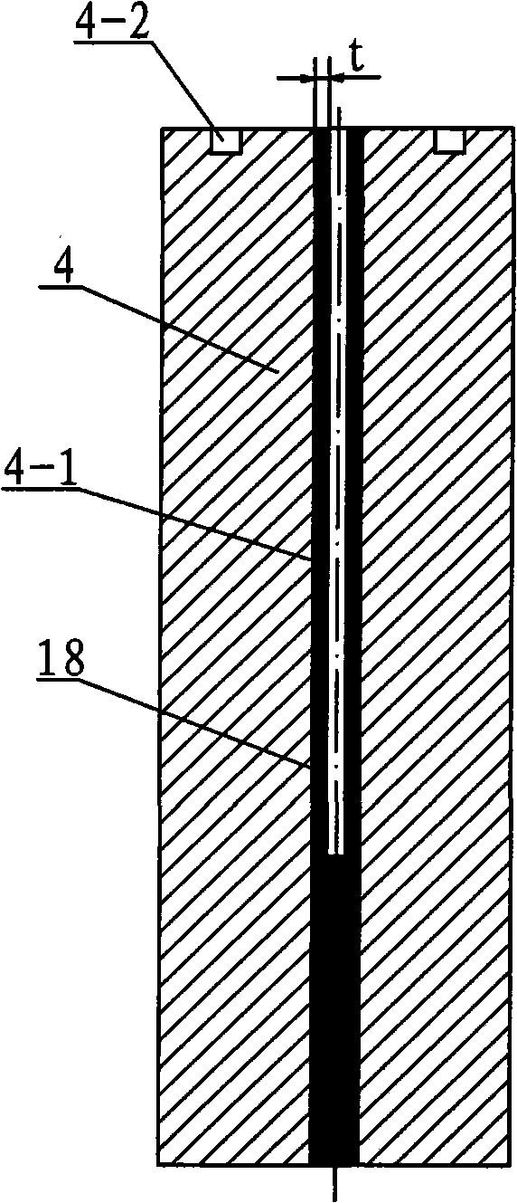
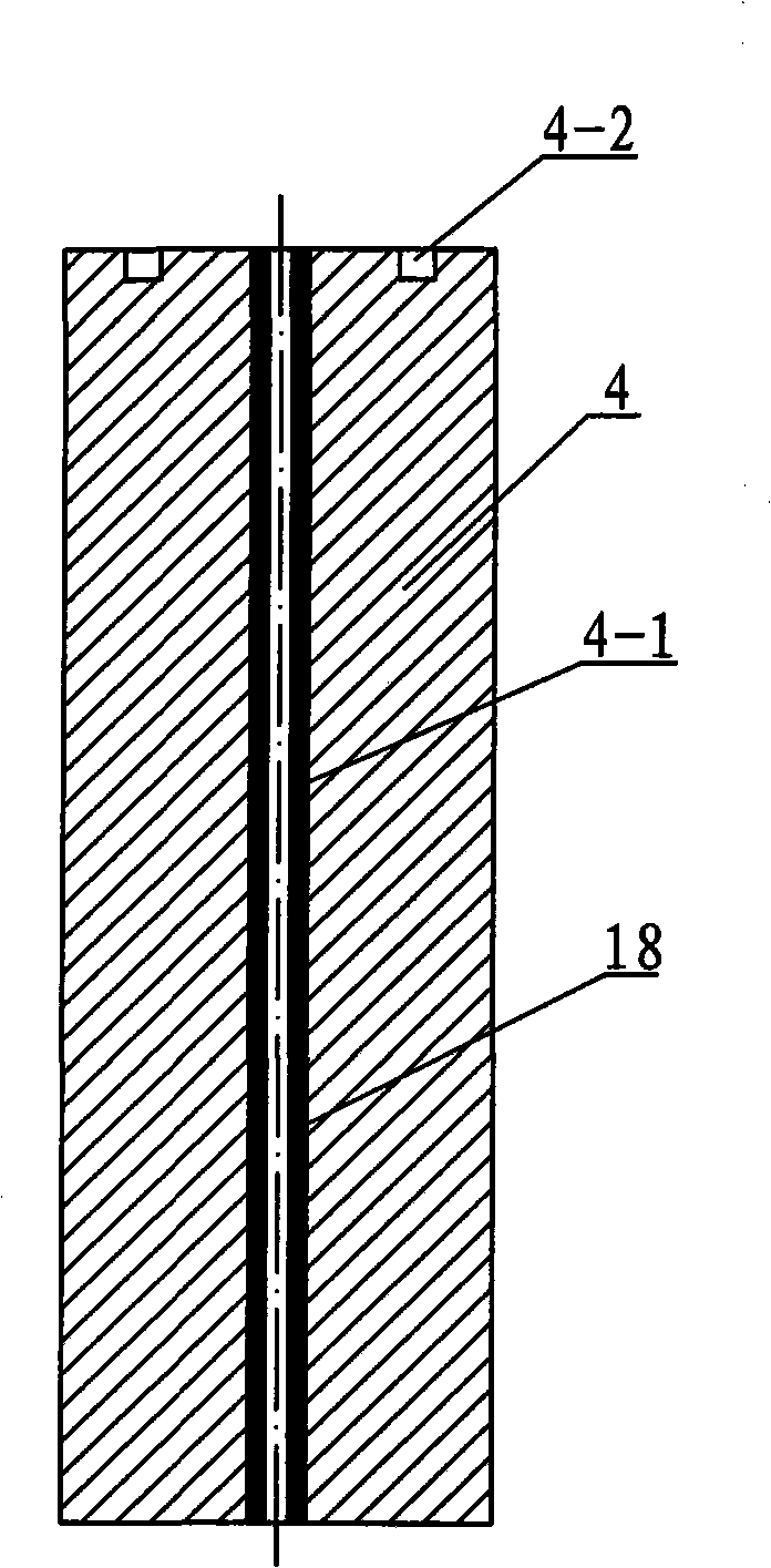
[0009] Specific implementation mode two: combination Figure 1 ~ Figure 3 The present embodiment will be described. The inner diameter of the cavity 4 - 1 of the die 4 of the present embodiment is Φ3 mm, and the length of the die 4 is 250 mm. The present invention is suitable for preparing thin-walled amorphous alloy tubes, and when the inner diameter of the mold cavity 4-1 and the length of the metal mold 4 are at the above-mentioned values, the thin-walled thin-walled elongated amorphous alloy tube has the best effect. Other components and connections are the same as those in the first embodiment.

specific Embodiment approach 3

[0010] Specific implementation mode three: combination figure 1 Describe this embodiment, the difference between this embodiment and specific embodiment one is: the device is also added with a gasket 16, the upper end surface of the metal mold 4 is provided with an annular groove 4-2, and the gasket 16 is installed in the annular groove 4-2. 2 in. This design increases the sealing performance between the lower end surface of the copper crucible 2 and the upper end surface of the metal mold 4 . Other components and connections are the same as those in the first embodiment.


PUM

PropertyMeasurementUnit
lengthaaaaaaaaaa
thicknessaaaaaaaaaa
lengthaaaaaaaaaa

Abstract

The invention provides a device and a method for shaping an amorphous alloy thin-wall slim pipe, and relates to a device and a method for shaping an amorphous alloy pipe. The invention aims at solving the problems that the thin-wall positions of the prior prepared amorphous alloy pipe can not fill and an inductive crucible easily reacts with the amorphous alloy. The device is a shaping device with a mold cavity, which is formed by the assembly of an arc-melting furnace, a copper crucible, a temperature measuring device, a suction casting valve, a mechanical pump, a tungsten electrode, a metal mold, a suction casting controller and a melting current controller. The method comprises the following steps: an alloy ingot is input; the vacuum degree is 5.0*10<-3>-6.0*10<-3>Pa; the melting current is 250-400A; and when the bottom temperature of the alloy ingot is more than the liquid-phase temperature, the suction casting controller opens the suction casting valve, the mechanical pump draws the air out of the inner cavity of the arc-melting furnace, the alloy liquid flows into the mold cavity, the alloy liquid in contact with the side wall forms a very thin metal scull on the side wall of the mold cavity, and the unsolidified alloy liquid in the center is drawn out of the mold. The invention is used for shaping of the slim alloy pipe.

Description

technical field [0001] The invention relates to a device and method for forming an elongated amorphous alloy tube. Background technique [0002] Amorphous alloys have excellent physical and chemical properties such as high elastic limit, high strength, high hardness, high wear resistance, and high corrosion resistance because they do not have a microstructure with long-range atomic order. At present, amorphous alloy tubes have been used as sensor components of mass flow meters. Amorphous alloy is a kind of rapid solidification material. The methods for preparing amorphous alloy pipe mainly include copper mold casting method, core pulling method and induction suction casting method. The copper mold casting method mainly injects amorphous alloy liquid into In the mold, so as to rapidly solidify and form an amorphous alloy pipe, the material of the amorphous alloy pipe mold is generally pure copper. The alloy tube method, the patent belongs to the copper mold casting method, ...

Claims


Application Information

Patent Timeline
Patent Type & Authority Applications(China)
IPC IPC(8): B22D18/06B22D18/08
Inventor 沈军魏先顺黄永江郑伟
Owner HARBIN INST OF TECH
Why Eureka
Try Eureka