
Bevel gear machining method

A processing method and technology of bevel gears, applied in the direction of belts/chains/gears, gear teeth, components with teeth, etc., can solve the problem that the constricted teeth arc teeth and quasi-involute bevel gears are not conjugated and cannot be ground. , expensive and other problems, to achieve the effect of small tool or grinding wheel diameter, small machine tool spindle torque, and small machine tool deformation

Active Publication Date: 2010-07-14
秦川机床工具集团股份公司 +1
View PDF10 Cites 37 Cited by
  • Summary
  • Abstract
  • Description
  • Claims
  • Application Information

AI Technical Summary

Problems solved by technology

[0023] 4) The cutting trajectory surface of the tool for processing cycloidal teeth and quasi-involute bevel gears is not a rotary surface, so the teeth cannot be ground;
[0024] 5) The shrinking arc teeth and quasi-involute bevel gears processed by the current method are theoretically not conjugate, and only approximate methods can be used, so it is difficult to control the contact spots and motion curves of the gear pair
[0025] The existing straight-toothed bevel gear planing method has low efficiency and cannot process large gears; double-cutter milling cannot process large gears due to tooth width restrictions; circular drawing tools are special, extremely expensive, and cannot process large gears

Method used


Image

  • Bevel gear machining method
  • Bevel gear machining method
  • Bevel gear machining method

Examples


Embodiment

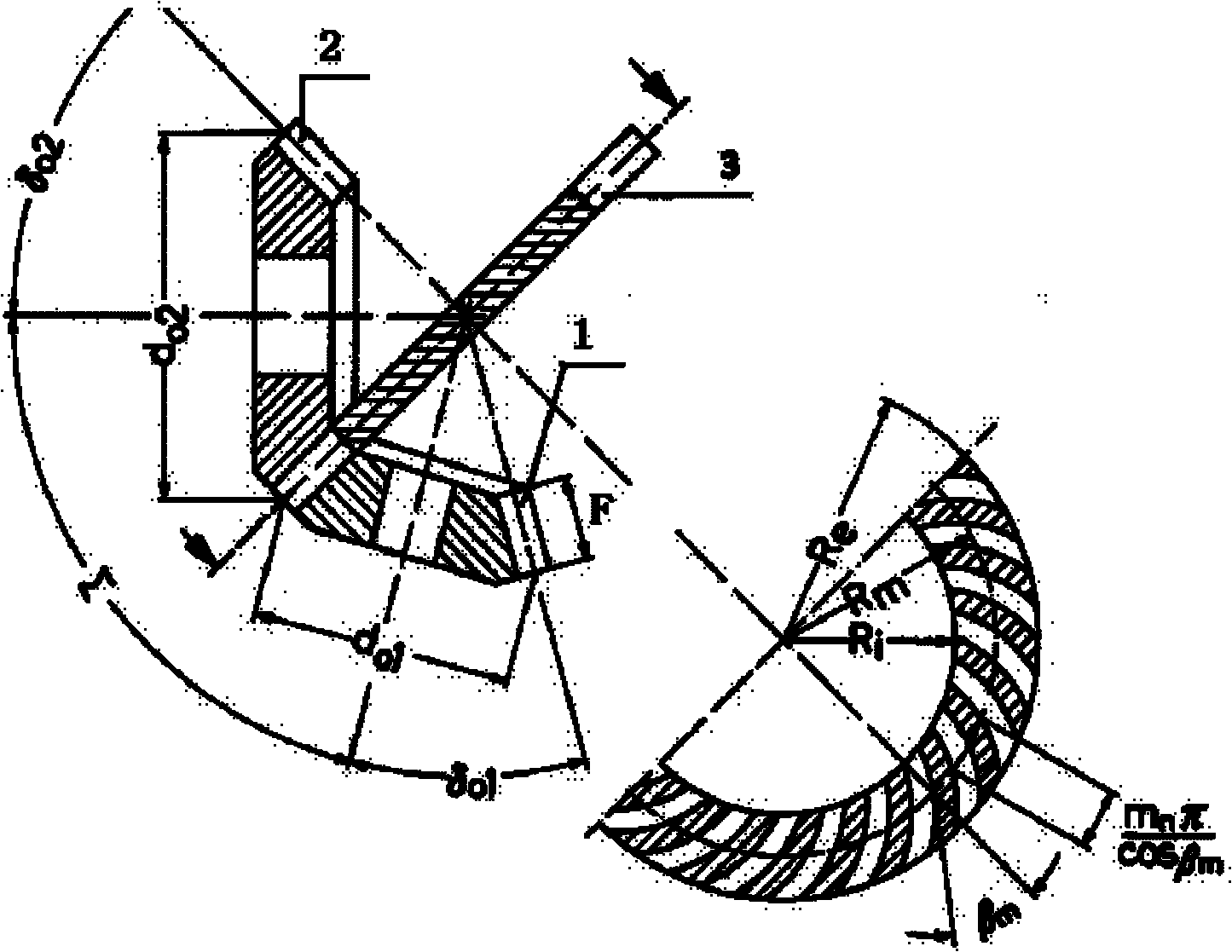
[0077] Embodiment: A pair of cycloidal bevel gears with equal height teeth were simulated and processed by the disc cutter according to the above method. Gear secondary shaft intersection angle ∑ = 90 degrees, large wheel 2 teeth number Z 2 =93, small wheel 1 tooth number Z 1 =25, big end face modulus M=27 mm, midpoint helix angle β m = 35 degrees, normal pressure angle α n =20 degrees, tooth width F=270 millimeters. The specific implementation is as follows:

[0078] (1) Determine the parameters of the shape wheel

[0079] Number of teeth

[0080] Adopt the plane shape wheel 3,

[0081]

[0082]

[0083] Midpoint radius R m Equal to the midpoint taper distance of the gear pair

[0084]

[0085] The midpoint helix angle is equal to the gear pair helix angle β m , is 35 degrees.

[0086] (2) Determine the gear tooth line. Cycloidal parameters depend on the number of teeth on the forming wheel, the radius of the cutter head and the number of sets of cutter ...


PUM


Abstract

The invention discloses a bevel gear machining method. According to the geometric parameters and the required tooth system of a gear to be machined, the method comprises the following steps that: (1) the parameters of a shaping gear wheel are determined; (2) the tooth traces of the shaping gear wheel are determined; (3) the parameters of a cutter are determined; (4) the cutter movement on the tooth surface of the shaping gear wheel is determined; (5) the basic tooth surface modification of the shaping gear wheel is determined; (6) the movement of the shaping gear wheel generating the gear is determined; (7) the movement of the gear generated by the shaping gear wheel is corrected; and (8) the generation of the gear to be machined is completed. The invention has the advantages that: (1) the cutting and the grinding of bevel gears with straight teeth, curved teeth, cycloidal teeth, quasi-involute teeth and the like can be implemented on one machine tool; (2) the dimension of the cutter is determined only by the module of the gear to be machined and has nothing to do with the diameter of the gear to be machined and the tooth width; (3) the diameter of the cutter or the grinding wheel is small, the torque of the machine tool spindle is small, the force applied to the machine tool is small, the deformation of the machine tool is small and the machining accuracy is high; (4) the position, the dimension and the shape of the contact spots on the tooth surface can be conveniently controlled and all kinds of theoretically full-conjugated bevel gear pairs can be machined; and (5) the transmission ratio function required by the gear pairs to be machined can be accurately realized.

Description

Technical field: [0001] The invention relates to a bevel gear processing method, which is a cutting and grinding processing method suitable for straight teeth and various curved bevel gears. Background technique: [0002] 1. Traditional bevel gear machining principles and methods [0003] There are two types of bevel gears: curved teeth and straight teeth. There are three main types of curved bevel gears: 1) shrinking arc gears, 2) cycloidal gears with equal heights and 3) quasi-involute bevel gears with equal heights. [0004] At present, the processing method of shrinking spiral bevel gears is represented by Gleason, and the machine tool shaker represents the production wheel. The cutting blades used are arranged on the same diameter on the same side. The common rotating surface of multiple blades during processing is the cutting The trajectory surface of the motion is the gear tooth surface. The tooth line of the profile wheel is an arc, and the tooth surface of the pr...

Claims


Application Information

Patent Timeline
IPC IPC(8): B23F1/00B23F5/00B23F9/00
Inventor 毛世民郭宝安李建刚田沙吴序堂龙兴元
Owner 秦川机床工具集团股份公司
Learn More