Hydraulic forming machine set for moulding and solidifying biomass

A technology of solidification liquid and mold forming, which is applied in the direction of material forming presses, presses, manufacturing tools, etc. It can solve the problems of low density of forming blocks, poor combustion performance, short service life, etc., and achieve high calorific value and molding density. High and long service life effect

Inactive Publication Date: 2010-07-14
江苏鼎绿科技有限公司
View PDF2 Cites 5 Cited by
  • Summary
  • Abstract
  • Description
  • Claims
  • Application Information

AI Technical Summary

Problems solved by technology

[0004] In order to solve the problems of complex structure, unstable operation, easy damage, short service life, low density of forming blocks and poor combustion performance in the existing technology, the purpose of the present invention is to provide a simple structure, stable operation, Biomass solidification liquid molding unit with long service life, high molding density, and good combustion performance of the molding block. This molding unit can be widely used for molding various biomass crop straw raw materials.

Method used


Image

  • Hydraulic forming machine set for moulding and solidifying biomass
  • Hydraulic forming machine set for moulding and solidifying biomass

Examples


Embodiment Construction

[0014] The present invention will be further described below in conjunction with drawings and embodiments.

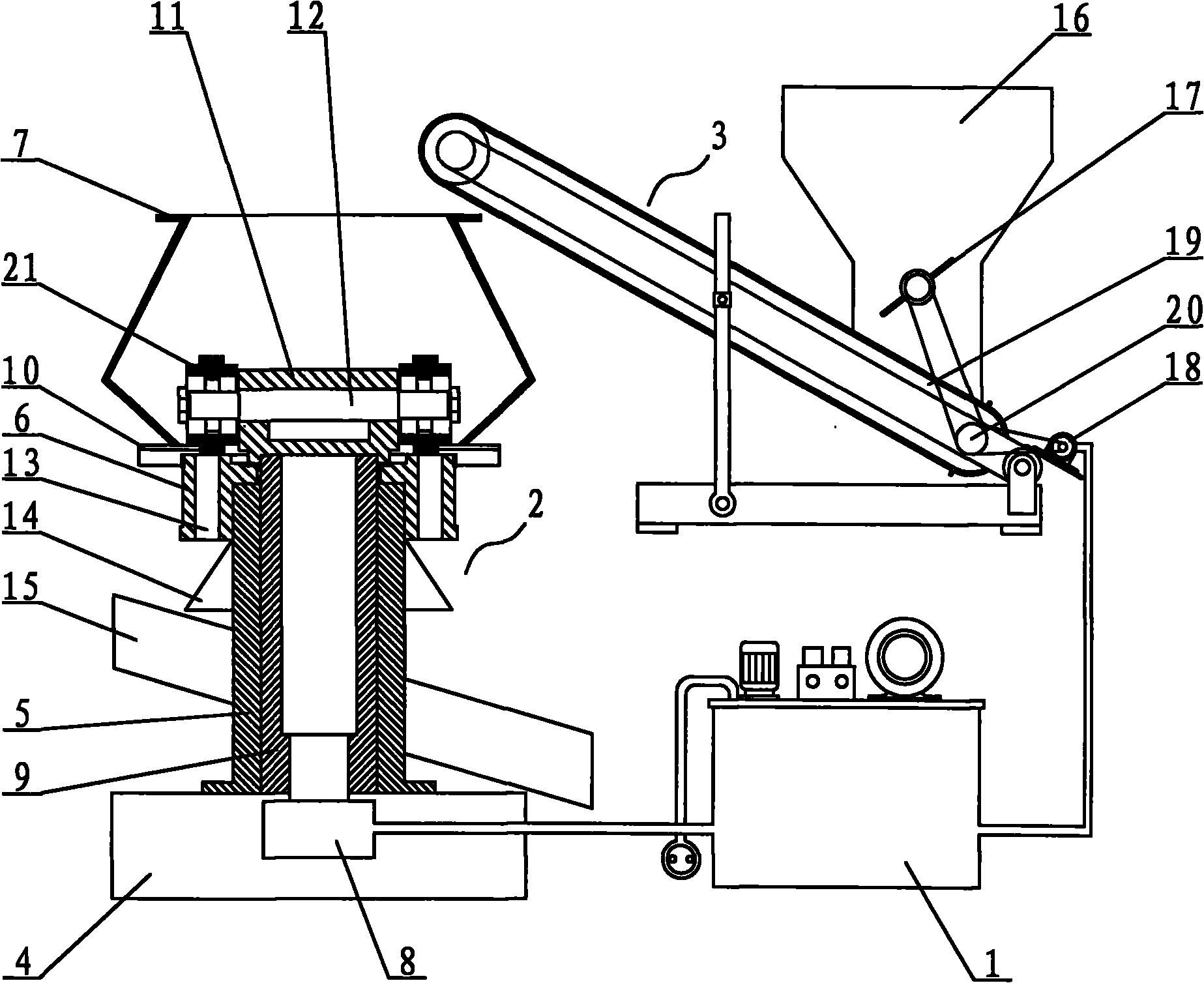
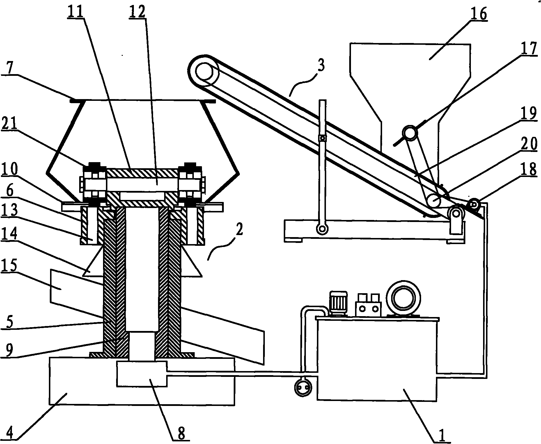
[0015] figure 1 The biomass solidification liquid molding unit shown mainly includes a molding machine 2, a feeding machine 3 and a hydraulic station 1 controlled by a control cabinet. The feeder 3 includes a hopper 16 and a conveyor belt 19, the hopper 16 is arranged above the conveyor belt 19, the hopper 16 is provided with a monolithic roller 17 for adjusting and feeding, the active rotating shaft 20 of the conveyor belt 19 is connected to the rotating shaft motor 18, The rotary shaft motor 18 is connected with the hydraulic station 1; the forming machine 2 includes a machine base 4, a support cylinder 5, a pressing plate 6 and an upper material cylinder 7, and a spindle motor 8 is arranged in the machine base 4, and the spindle motor 8 is connected with the hydraulic station 1, The supporting cylinder 5 is provided with a main shaft 9 vertically connected to the sp...


PUM


Abstract

The invention relates to a hydraulic forming machine set for moulding and solidifying biomass, which comprises a hydraulic station, a feeder, a forming machine and a control cabinet, wherein the feeder comprises a hopper and a conveyer belt; the forming machine is formed by connecting a base, a support cylinder and a die pressing device sequentially; a main shaft is arranged in the support cylinder; the die pressing device comprises a die pressing plate, a connecting plate, a pinch roller shaft and two pinch rollers; the die pressing plate is sleeved at the top end of the support cylinder; a circle of circular discharging die holes are formed on the die pressing plate; the top end of the main shaft is connected with the connecting plate; the pinch roller shaft runs through the connecting plate horizontally; the pinch rollers are respectively sleeved at both ends of the pinch roller shaft; and a track formed by rotating the pinch rollers around the main shaft is positioned above the discharging die holes of the die pressing plate and is in clearance fit with the upper surface of the die pressing plate. The hydraulic mould forming machine set is driven by full hydraulic power, and the pinch rollers perform rotation while performing revolution, so that the biomass is formed by rolling compaction through the discharging die holes, and the hydraulic forming machine set has the advantages of simple integral structure, high hydraulic power, low energy consumption, long service life, good effect of rolling compaction, high density of formed blocks and good burning effect, and is suitable for forming various biomass straws.

Description

technical field [0001] The invention relates to a biomass molding unit, in particular to a molding unit for hydraulic power, molding and solidification of biomass raw materials. Background technique [0002] my country is rich in agricultural surplus resources, and most of the harvested straws are piled up for storage, which is easy to cause fire and poses a safety hazard. Even if it is burned centrally, it will also cause serious environmental pollution. At present, straw and other biomass raw materials are made into fuel blocks to replace coal as a new type of fuel, which solves the problems of air pollution caused by straw burning in rural areas and lack of coal resources. [0003] A kind of straw rolling forming machine disclosed as CN200910016137.5 as the patent application number adopts the contact surface of two ring dies with ring die holes as the extrusion working surface, fed by the hopper above the extrusion working surface, and the two The ring dies rotate each ...

Claims


Application Information

Patent Timeline
Patent Type & Authority Applications(China)
IPC IPC(8): B30B11/20B30B15/06B30B15/30
CPCB30B11/228
Inventor 吕文龙王正元
Owner 江苏鼎绿科技有限公司
Why Eureka
Try Eureka