
Micro-pore aeration system

A technology of microporous aeration and air distribution pipes, applied in water aeration, sustainable biological treatment, water/sludge/sewage treatment, etc., can solve performance and technical deficiencies, large impact area, increase air resistance loss, etc. problems, achieve high oxygenation efficiency and power efficiency, low production cost, and long service life

Active Publication Date: 2012-04-18
广西南亚科技有限公司
View PDF0 Cites 0 Cited by
  • Summary
  • Abstract
  • Description
  • Claims
  • Application Information

AI Technical Summary

Problems solved by technology

[0004] 1. The former is prone to water ingress in the micropores during the alternating start and stop of aeration operation, resulting in microbial growth and blockage and inconvenient cleaning. The latter is prone to fatigue and rupture of the rubber membrane due to the continuous expansion and contraction of the pore diameter during the aeration process, which cannot be repaired;
[0005] 2. Due to the gradual blockage of the aeration micropores or the aging and hardening of the rubber, the rated aeration volume will decrease, which will increase the air resistance loss and increase the power consumption;
[0007] 4. The service life is short, generally about 5 years, which is far behind the surface aeration equipment with a service life of about 15 years and easy maintenance;
[0008] 5. Replacing or cleaning damaged or clogged microporous aeration equipment requires heavy workload, high cost, long cycle and large impact
[0009] The above-mentioned shortcomings of microporous aeration equipment are the main reasons for the increase in management and maintenance costs of sewage treatment. Compared with surface aeration equipment, the economic benefits of comprehensive operation are not in an advantageous position. These shortcomings are due to the current equipment material performance and technology. It is also difficult to improve and break through on the original basis.

Method used


Image

  • Micro-pore aeration system
  • Micro-pore aeration system
  • Micro-pore aeration system

Examples


Embodiment Construction

[0033] The present invention will be further described below in conjunction with the accompanying drawings and embodiments.

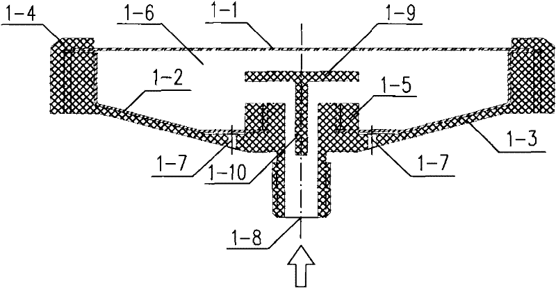
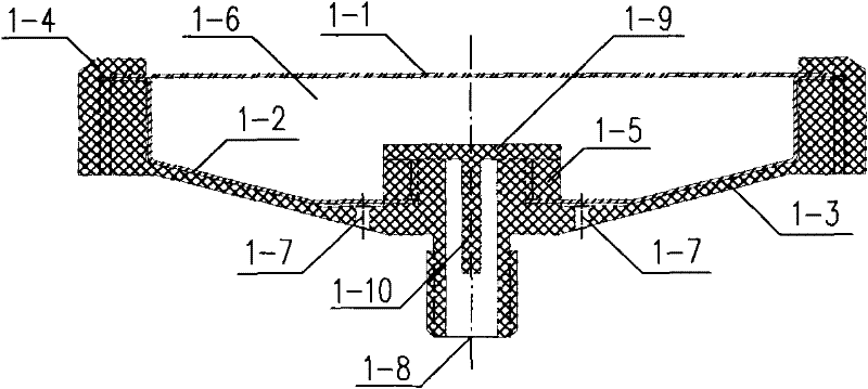
[0034] When the pipeline system is equipped with a water seal safety device, the lifting check valve plate 1-9 and the positioning slide bar 1-10 of the microporous aeration device 1 can be cancelled.

[0035] 1. System flow

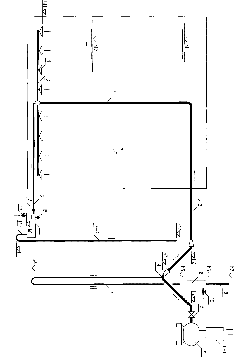
[0036] A microporous aeration system is used for aerobic aeration in sewage biochemical treatment.

[0037] According to Figure-1 and the above, the working conditions of the present invention are divided into aeration operating conditions, intermittent working conditions and initial working conditions, which are described as follows:

[0038] 1. Aeration operating conditions

[0039] After the air is cleaned by the air filter 6-1, it is pressurized by the blower 6, and passes through the main valve 5, the Y-shaped tee pipe 4, the air supply main pipe 3-2, 3-1, the air distribution pipe network 2, and the microporous aeration T...


PUM

PropertyMeasurementUnit
pore sizeaaaaaaaaaa

Abstract

The invention discloses a micro-pore aeration system, which is used for the bottom aerobic aeration of the sewage biological treatment, and mainly consists of a micro-power aeration device, an air distribution pipe network, an air supply main pipe, a water-sealing safety device, a main valve, a blower, an air filter and an end drain device. The micro-pore aeration device mainly consists of a hydrophobic effect micro-pore aeration diaphragm, a soft capsule, an elevation-type check valve plate, a press cover and a base; the water-sealing safety device consists of a Y-shaped tee pipe, a U-shapedpipe, an adjusting pipe and a pressure stabilizing pipe; and the end drain device mainly consists of a drain tank, a drain pipe, a drain valve, a discharging pipe and an air release valve. Compared with the similar advanced technologies both at home and abroad, the micro-pore aeration system has the advantages that the service life is greatly prolonged, while the aeration efficiency is improved and the running power consumption is reduced, and the service life can reach more than 20 years, so the total cost of the sewage treatment is greatly reduced, and the vast economic benefit can be realized.

Description

technical field [0001] The invention relates to a sewage treatment technology, in particular to a microporous aeration system for sewage biochemical treatment. Background technique [0002] There are two main types of aeration equipment for sewage treatment: surface aeration equipment such as pump (umbrella) type, rotary brush (disk) and bottom aeration equipment such as microporous aerator (tube), cyclone aerator, diffuse flow aerator, etc. Aeration equipment. Microporous aeration equipment has high power efficiency, more than twice that of surface aeration equipment, which can greatly reduce the operating power consumption of sewage treatment, and has been widely used in engineering. [0003] Microporous aeration equipment is roughly divided into two types: corundum microporous aeration equipment with fixed pore diameter and rubber microporous aeration equipment with variable pore diameter. There are the following disadvantages during use: [0004] 1. The former is prone...

Claims


Application Information

Patent Timeline
Patent Type & Authority Patents(China)
IPC IPC(8): C02F3/02C02F7/00
CPCY02W10/10
Inventor 何际跃
Owner 广西南亚科技有限公司
Learn More