Latent heat recoverable multi-phase change sludge drying method and device

A technology of sludge drying and multiphase transformation, which is applied in the latent heat recovery type multiphase transformation sludge drying and reduction treatment, and the harmless treatment of excess sludge in urban sewage treatment plants. Utilization, untreated drying tail gas, high energy consumption and other problems, to achieve the effect of reducing drying cost, good energy saving effect and high heat transfer efficiency

Active Publication Date: 2010-07-14
SHENYANG INST OF AERONAUTICAL ENG
View PDF0 Cites 56 Cited by
  • Summary
  • Abstract
  • Description
  • Claims
  • Application Information

AI Technical Summary

Problems solved by technology

[0006] In order to overcome the deficiencies in the existing sludge drying technology, such as large energy consumption, non-recovery and reuse of sludge steam latent heat, and untreated drying tail gas, the present invention provides a latent heat recovery type multi-phase change sludge drying method and realizes the The equipment used in the method is to combine the low-temperature steam rotary disc dryer with the sludge waste steam latent heat recovery heat pump and the tail gas purification device. Through the control of process parameters, the energy balance of the drying device can be realized, and the cost of sludge drying can be reduced and the latent heat can be recovered. The purpose of reuse and tail gas purification treatment, and to provide favorable conditions for the subsequent treatment and disposal of sludge and resource utilization

Method used


Image

  • Latent heat recoverable multi-phase change sludge drying method and device
  • Latent heat recoverable multi-phase change sludge drying method and device
  • Latent heat recoverable multi-phase change sludge drying method and device

Examples


Embodiment

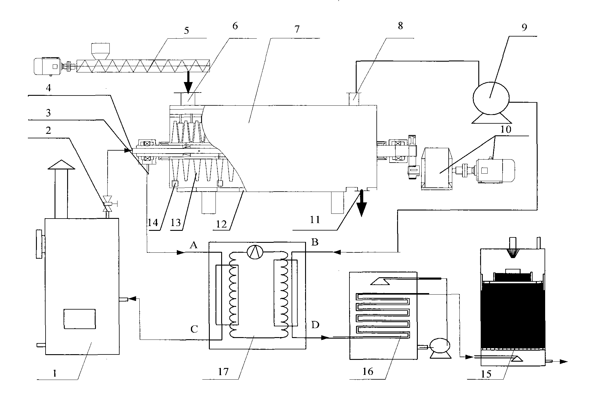
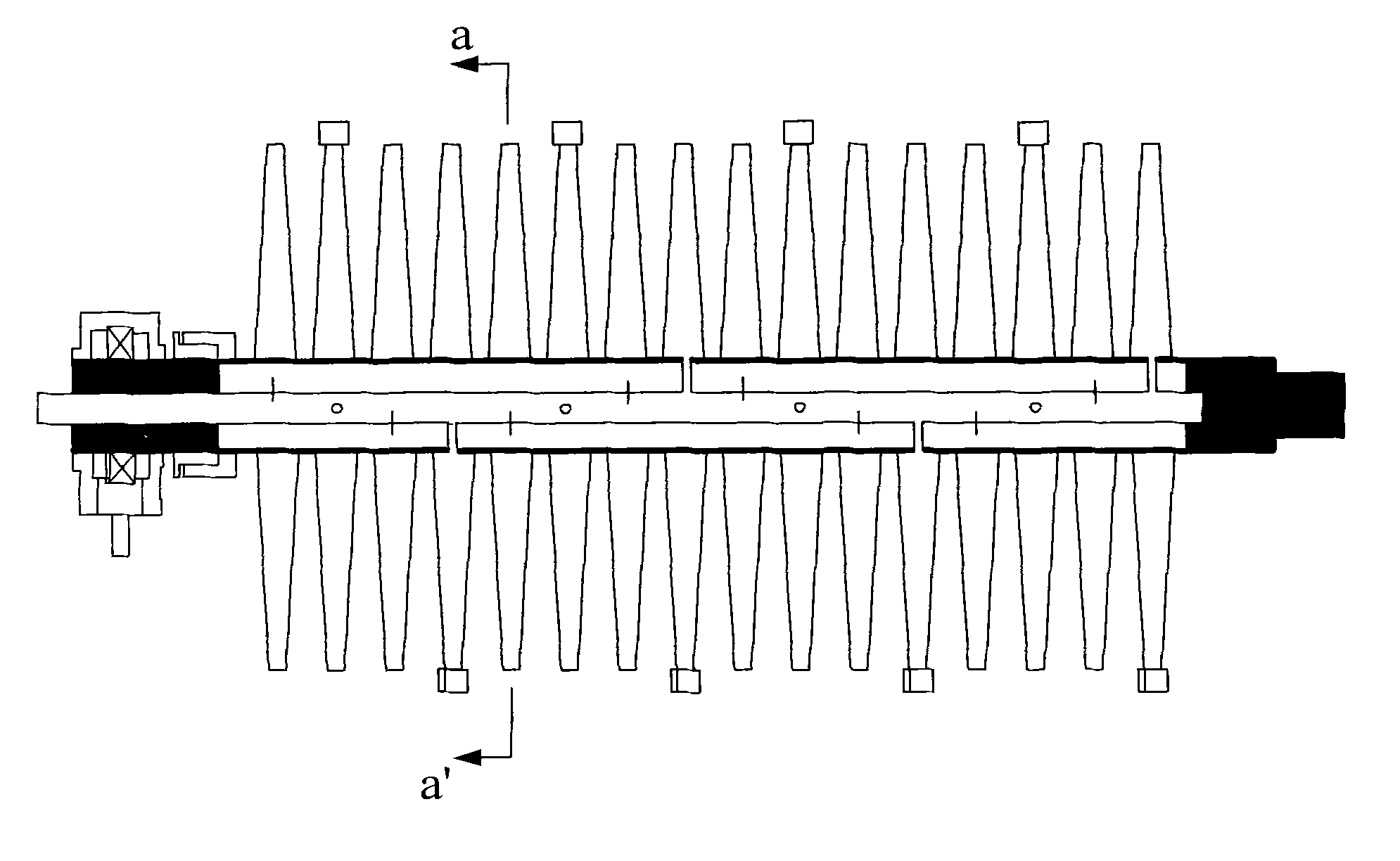
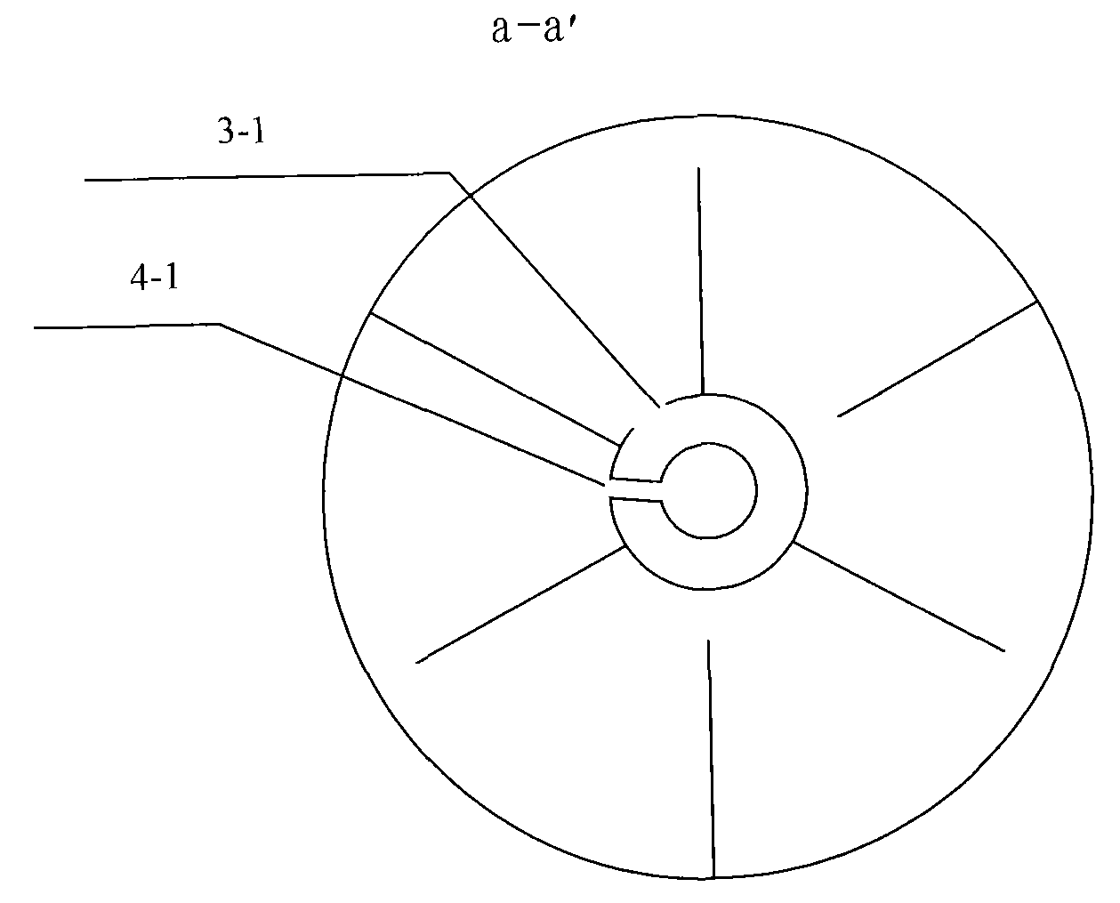
[0035]The mechanically dewatered sludge (with a moisture content of about 80%) stored in the sludge hopper is sent into the rotary sludge dryer 7 through the screw feeder, and the sludge is dried by the rotation of the deflector 14 on the hollow disc 13 Turn over, stir, constantly update the heating interface, contact the inner wall of the cylinder and the hollow disk 13, and be fully heated to evaporate the surface water contained in the sludge (sludge waste steam), and discharge it from the exhaust outlet 8 of the dryer. The dried sludge moves forward under the forward force of the deflector 14 and is discharged at the sludge outlet 11 of the drying machine. The heat required for sludge drying comes from the water vapor generated by the steam generator 1. The water vapor enters the disk cavity from the steam inlet 4-1 of the steam pipe 4 of the dryer, and undergoes sufficient phase conversion heat in the cavity, and The sludge is dried by heat conduction, and the steam after...


PUM


Abstract

The invention discloses a latent heat recoverable multi-phase change sludge drying method and a latent heat recoverable multi-phase change sludge drying device, which are designed for solving the technical problems that the energy consumption is high, the latent heat of the sludge vapor cannot be recovered and reused, the dried tail gas pollutes the environment, the operating cost is high and the like in the conventional sludge drying technology. Due to the combination of a low-temperature vapor turntable dryer, a sludge waste vapor latent heat recover heat pump and a tail gas purification device, and the use of indirect phase change heat exchange for low-temperature vapor, the heat exchange is improved, and the loss of organic components of the sludge is low. The latent heat of the sludge drying tail gas is recovered by using the latent heat recover heat pump, and the recovered heat energy is reused for sludge drying. Therefore, the heat efficiency is improved, the operating cost is reduced, and the problems that the heat utilization ratio is low, the operating cost is high and the like in the sludge drying process are better solved. The dried products meet the requirement of baking light and energy-saving bricks and producing cement laminated products, and over 90 percent of heat value of the original sludge is maintained. Therefore, the resource utilization value of the sludge is maximized.

Description

technical field [0001] The present invention relates to a sludge drying method and equipment, in particular to a latent heat recovery type multi-phase change sludge drying method and equipment, especially suitable for harmless and reduction of residual sludge in urban sewage treatment plants processing. Background technique [0002] At present, more than 90% of urban sewage treatment plants use the activated sludge method, accompanied by a large amount of excess sludge. According to statistics, the amount of sludge produced by domestic sewage treatment in my country alone reaches hundreds of millions of tons every year; in addition, industrial processes such as chemical, papermaking and pharmaceuticals, and dredging of rivers and lakes also produce a large amount of sludge. Usually the remaining sludge has the characteristics of high water content (97%), perishable and smelly, and contains toxic and harmful substances such as pathogenic bacteria, parasite eggs, heavy metals...

Claims


Application Information

Patent Timeline
Patent Type & Authority Applications(China)
IPC IPC(8): C02F11/12C02F11/18F24J3/00B01D53/78B01D53/83
CPCY02B30/123Y02B30/52Y02W10/37
Inventor 李润东孙洋岳东北王洪涛
Owner SHENYANG INST OF AERONAUTICAL ENG
Why Eureka
Try Eureka