Optical fiber temperature/humidity sensor inductive layer and preparation method and application thereof

A technology of humidity sensor and sensing layer, which is applied in the field of sensors, can solve the problems of increasing the difficulty of the process, and achieve the effects of meeting the requirements of sensor detection, obvious economic benefits, and high product quality

Inactive Publication Date: 2010-07-14
SOUTH CHINA UNIV OF TECH
View PDF7 Cites 12 Cited by
  • Summary
  • Abstract
  • Description
  • Claims
  • Application Information

AI Technical Summary

Problems solved by technology

Due to the need to control the temperature of the liquid material during the coating process, it increases the difficulty of the process

Method used


Image

  • Optical fiber temperature/humidity sensor inductive layer and preparation method and application thereof
  • Optical fiber temperature/humidity sensor inductive layer and preparation method and application thereof
  • Optical fiber temperature/humidity sensor inductive layer and preparation method and application thereof

Examples


Embodiment approach

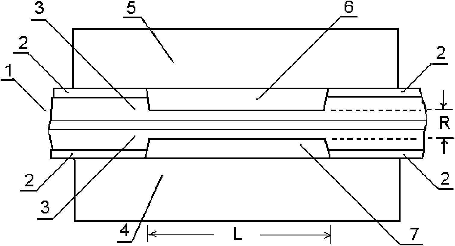
[0033] figure 1 An embodiment of the present invention is shown, and the preparation method of the sensing layer of the optical fiber humidity sensor specifically includes the following steps:

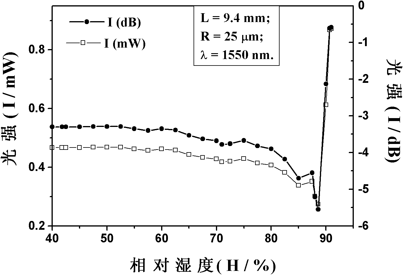
[0034] (1) Form an optical fiber sensing section with a smaller outer diameter on the optical fiber 1, the two ends of the optical fiber sensing section are optical fibers provided with a protective jacket, and the outer diameters of both ends are greater than the outer diameter of the optical fiber sensing section; It is a commercially available step-type optical fiber, the model is Corning SMF-28e bare fiber, the length of the optical fiber sensing section is L as shown in the figure, remove the protective layer 2 on the optical fiber sensing section with optical fiber pliers, and use 5% to 40% hydrogen Fluoric acid corrodes part of the optical fiber cladding 3, and the outer diameter of the remaining cladding is R as shown in the figure;

[0035] (2) The optical fiber sensing secti...

Embodiment 2

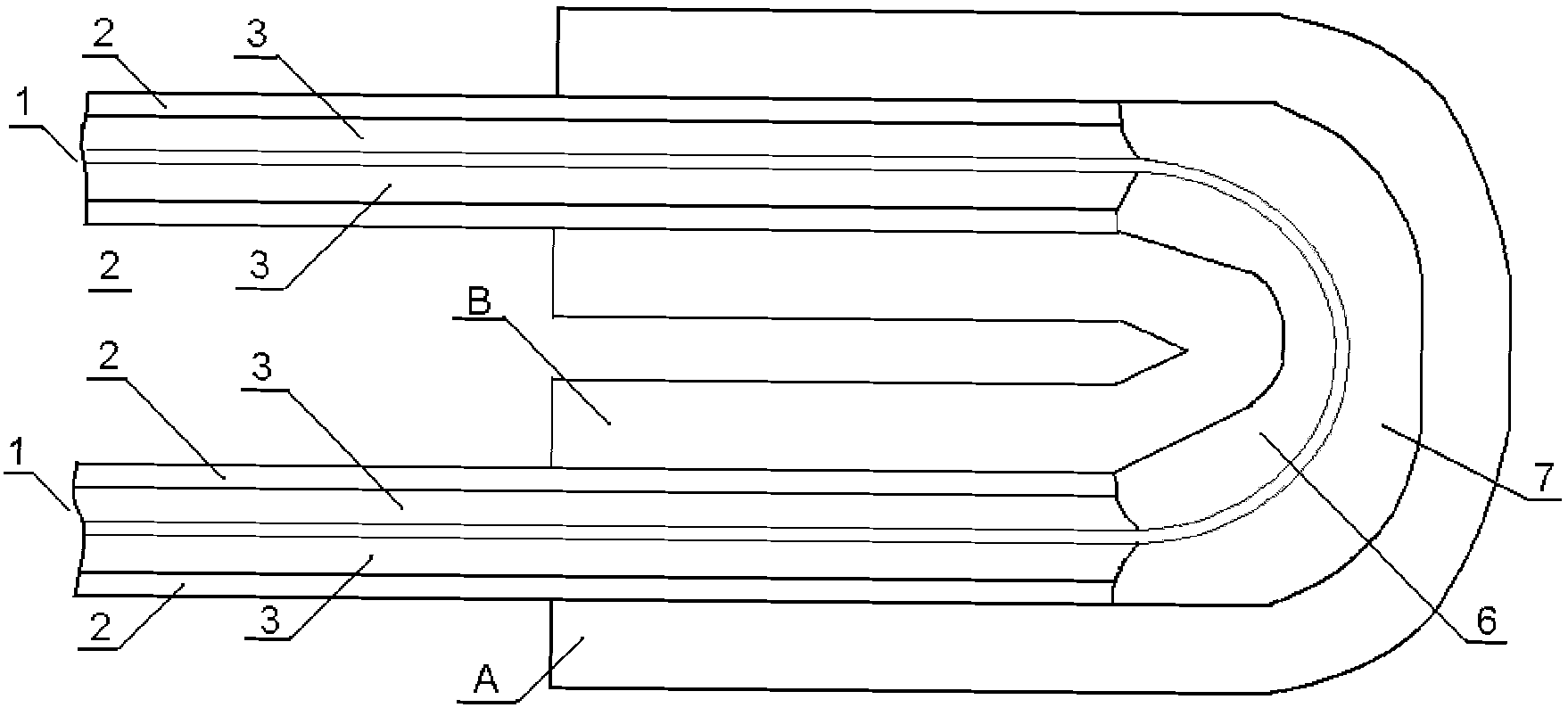
[0041] image 3 Another embodiment of the present invention is shown. The method for preparing the sensing layer of the optical fiber temperature / humidity sensor specifically includes the following steps:

[0042] (1) An optical fiber sensing section with a smaller outer diameter is formed on the optical fiber 1, and the two ends of the optical fiber sensing section are optical fibers provided with a protective coating / protective jacket, and the outer diameters of both ends are larger than the outer diameter of the optical fiber sensing section , the optical fiber sensing section is fixed in a U-shape; the optical fiber is a YOFC Chuangyou multimode bare fiber, and the protective layer 2 on the optical fiber sensing section is removed with fiber optic clamps, and corroded with 5% to 40% hydrofluoric acid Fiber cladding 3;

[0043] (2) Set the U-shaped optical fiber sensing section between two independent U-shaped metal wires, the bending inner diameter of U-shaped metal wire ...

Embodiment 3

[0047] Figure 4 Another embodiment of the present invention is shown. The method for preparing the sensing layer of the optical fiber temperature / humidity sensor specifically includes the following steps:

[0048] (1) Optical fiber 1 uses a commercially available single-mode bare fiber, removes the protective layer 2 on the sensing section L with fiber optic pliers, and fabricates a fiber grating on the sensing section L;

[0049] (2) The fiber grating is placed between two independent plastic fibers C and D, and is also in the middle of the plastic fibers C and D in the axial direction of the optical fiber. The length of the grating is 2cm (1cm at both ends), and the outer diameters of the two independent plastic fibers C and D are larger than the outer diameter of the fiber grating;

[0050] (3) Attach two independent plastic fibers C and D to the optical fiber 1 and fix them together. The specific fixing method can be clamped with a clamp to clamp the support and the prot...


PUM

PropertyMeasurementUnit
lengthaaaaaaaaaa

Abstract

The invention provides a preparation method of an optical fiber temperature/humidity sensor inductive layer, which comprises the following steps of: forming an optical fiber sensing segment with smaller outside diameter on an optical fiber, forming a rail at the periphery of the optical fiber sensing segment which is positioned in the rail, filling a liquid material in the rail, forming a layer of liquid film, wrapping the optical fiber sensing segment in the liquid film and coating an inductive layer on the outer surface of the optical fiber sensing segment. The optical fiber temperature/humidity sensor inductive layer manufactured by utilizing the preparation method of the optical fiber temperature/humidity sensor inductive layer is applied to producing an optical fiber temperature/humidity sensor. The invention has the advantages of simple process, easy operation, low manufacturing cost and good applicability.

Description

technical field [0001] The invention relates to the sensor technology for realizing temperature / humidity detection by using optical fiber, in particular to the sensing layer of the optical fiber temperature / humidity sensor and its preparation method and application. Background technique [0002] The optical fiber temperature / humidity sensor can convert the temperature / humidity of the environment into an optical signal, and then convert it into an electrical signal that is easy to process, display and record at the terminal after optical fiber transmission, thereby realizing remote detection and control of temperature / humidity. Due to the unique advantages of strong anti-electromagnetic interference and good insulation performance, optical fiber sensors are widely used in storage, process control, petroleum, chemical and electric power environmental monitoring, especially in the research of soil erosion, forest vegetation and desertification. In the field, soil and water cons...

Claims


Application Information

Patent Timeline
Patent Type & Authority Applications(China)
IPC IPC(8): G01K11/32G01N21/41G02B6/02G01K11/3206
Inventor 张小康兰璐孔镇陈丽华叶智仁
Owner SOUTH CHINA UNIV OF TECH
Why Eureka
Try Eureka