
Method for analyzing and detecting pathogenic microorganisms

A pathogenic microorganism and bioluminescence technology, applied in the field of micro-total analysis technology in the field of biological analysis, can solve the problems of strict culture environment and operator requirements, unsuitable rapid detection of pathogenic bacteria, accumulation of operating errors, etc., to ensure the detection range and avoid samples. loss, the effect of reducing operating errors

Inactive Publication Date: 2010-07-14
ARMY MEDICAL UNIV
View PDF0 Cites 16 Cited by
  • Summary
  • Abstract
  • Description
  • Claims
  • Application Information

AI Technical Summary

Problems solved by technology

At present, conventional pathogenic microorganism detection methods mainly include culture method, immunological detection method and molecular biology method, and all of them have many deficiencies due to the limitations of their own research methods: traditional bacterial culture methods and biochemical identification methods have low specificity , Time-consuming and labor-intensive, strict requirements on the culture environment and operators, not suitable for rapid detection of pathogenic bacteria
However, the existing technologies and methods are mainly aimed at a certain unit or step in the analysis and detection of pathogenic microorganisms, such as enrichment / sorting, pretreatment or separation detection, that is, the detection usually needs to be completed in several times, and there are a lot of operations Errors accumulate, and there are disadvantages such as long analysis time and large sample loss, large detection error, long time, and large amount of drugs and reagents consumed during detection

Method used


Image

  • Method for analyzing and detecting pathogenic microorganisms
  • Method for analyzing and detecting pathogenic microorganisms
  • Method for analyzing and detecting pathogenic microorganisms

Examples


Embodiment 1

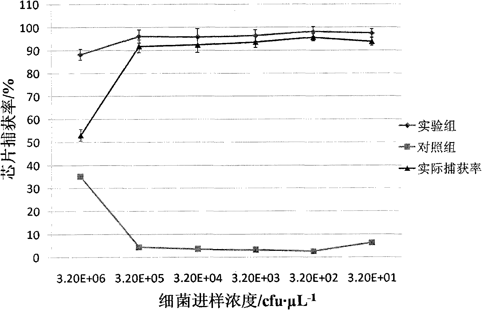
[0038] Example 1 :use figure 1 Chips shown for E.coli O157:H7 capture / enrichment studies

[0039] Use 0.01mol L -1 PBS Press 10, 10 2 , 10 3 , 10 4 , 10 5 After fully suspended, take 1 μL of the above-mentioned bacterial suspension (the concentration of the bacterial solution is shown in Table 1) and add it to the inlet storage tank, and the concentration is 5 μL·min. -1 The flow rate is driven by positive pressure into the microchannel of the chip, and then 0.01mol L with pH=7.20 -1 PBS at 10 μL·min -1 Flush the microchannel for 5 min at a flow rate. In the whole study, the microbead chip filled with antibody modification was used as the experimental group, and the microbead chip filled with BSA blocked as the control group. Using the plate counting method, culture and count the bacterial sample injection liquid and the flushing liquid collected in the outlet reservoir, according to the formula:

[0040]

[0041] Calculate the capture rate and the adsorption rat...

Embodiment 2

[0046] Example 2 : Bioluminescence detection of standard strain E.coli O157:H7

[0047] Use 0.01mol L -1 Diluted 10 times with PBS buffer, the bacterial concentration was 10 5 cfu μL -1 . Take 1 μL of the bacterial suspension and add it to the inlet reservoir of the chip. -1 The flow rate is driven into the chip by positive pressure, and then 0.01mol L with pH=7.20 -1 PBS buffer at 10 μL min -1 Flush at a flow rate of 5 minutes to reduce or eliminate non-specific adsorption or residues on the chip wall and in the gap between microbeads. The bioluminescence reagent (BacTiter-Glo TM Microbial Cell Viability Assay, Promega, USA) at 1 μL min -1 The positive pressure of the flow rate is transmitted to the chip, and the luminescence intensity is detected at the chip outlet reservoir as the luminescence detection point, and the signal is collected by the PMT optical signal detector, and the typical luminescence curve is as follows: image 3 shown.

[0048] According to th...

Embodiment 3

[0051] Example 3: Bioluminescent detection of E.coli O157:H7 in food samples

[0052] Take two portions of clean pork, 5g each, cut into 1mm in a sterile environment 3 Left and right pieces. Add two portions of pork to two sterilized centrifuge tubes, then add 1000 μL of E.coliO157:H7 that has been proliferated for 8 hours and dilute 10 3 times E.coli O157:H7 1000μL each, and 0.01mol·L -1 PBS 4mL each one. After the above two groups of pork samples containing different concentrations of bacterial suspension were vortexed and mixed, they were centrifuged at 1000 rpm for 5 minutes, and then 1 μL of supernatant (see Table 3 for the concentration of the injected bacterial solution) was added to the chip inlet reservoir. , at 5 μL·min -1 The flow rate is driven into the chip by positive pressure, and then 0.01mol L with pH=7.20 -1 PBS buffer at 10 μL min -1 Rinse at flow rate for 5 minutes. The bioluminescent reagent was added at 1 μL min -1 The positive pressure of the flow ...


PUM


Abstract

The invention relates to a method for analyzing and detecting pathogenic microorganisms, which comprises the following steps: (1) filling immunological microspheres modified by antibodies into an immunological recognition / enrichment cavity; (2) introducing a sample solution to be measured into the immunological recognition / enrichment cavity to be recognized, captured and enriched by the immunological microspheres; (3) respectively transferring a cracking agent and a biological luminous reagent into the immunological recognition / enrichment cavity to carry out cracking reaction and biological luminous reaction with the enriched pathogenic microorganisms to generate a luminous composite; and (4) eluting the luminous composite generated in the step (3) with a buffer solution, and analyzing the pathogenic microorganisms in the sample to be measured through luminous detection. The method realizes separation / enrichment, inclusion cracking, biological luminous reaction and quantitative detection of the pathogenic microorganisms on the same micro-fluidic chip, not only reduces the consumption of the sample and the reagent but also avoids complicated operation, overlong analysis time and sample loss caused by a plurality of analysis steps or processes, and improves the analysis speed, the detection accuracy and the detection sensitivity.

Description

technical field [0001] The invention belongs to the application of micro-total analysis technology in the field of biological analysis, in particular to a method for analyzing and detecting pathogenic microorganisms based on microfluidic chip technology. Background technique [0002] Strongly pathogenic pathogenic microorganisms are often highly pathogenic, such as enterohaemorrhagic Escherichia coli O157:H7 (E.coli O157:H7), the minimum infectious dose can be less than 10 pathogenic bacteria. Therefore, the development of rapid, sensitive and specific analysis and detection methods for pathogenic microorganisms in the environment, food and clinical specimens is an urgent need for human society to prevent the spread of infectious diseases and ensure human health. At present, conventional pathogenic microorganism detection methods mainly include culture method, immunological detection method and molecular biology method, and all of them have many deficiencies due to the limit...

Claims


Application Information

Patent Timeline
IPC IPC(8): G01N21/76G01N33/53
Inventor 张惠静管潇毕颖楠张莉郝敦玲
Owner ARMY MEDICAL UNIV
Learn More