
Laminated composite solar battery

A technology of solar cells and laminated structure, applied in the field of solar photovoltaic utilization, can solve the problems of low efficiency and unstable performance, etc.

Inactive Publication Date: 2010-07-14
PEKING UNIV
View PDF0 Cites 7 Cited by
  • Summary
  • Abstract
  • Description
  • Claims
  • Application Information

AI Technical Summary

Problems solved by technology

However, the efficiency of polymer solar cells developed at present is generally still relatively low, all below 5%, and the performance is not stable yet.

Method used


Image

  • Laminated composite solar battery
  • Laminated composite solar battery
  • Laminated composite solar battery

Examples


Embodiment Construction

[0022] The specific implementation manners of the present invention will be further described in detail below in conjunction with the accompanying drawings and embodiments. The following examples are used to illustrate the present invention, but are not intended to limit the scope of the present invention.

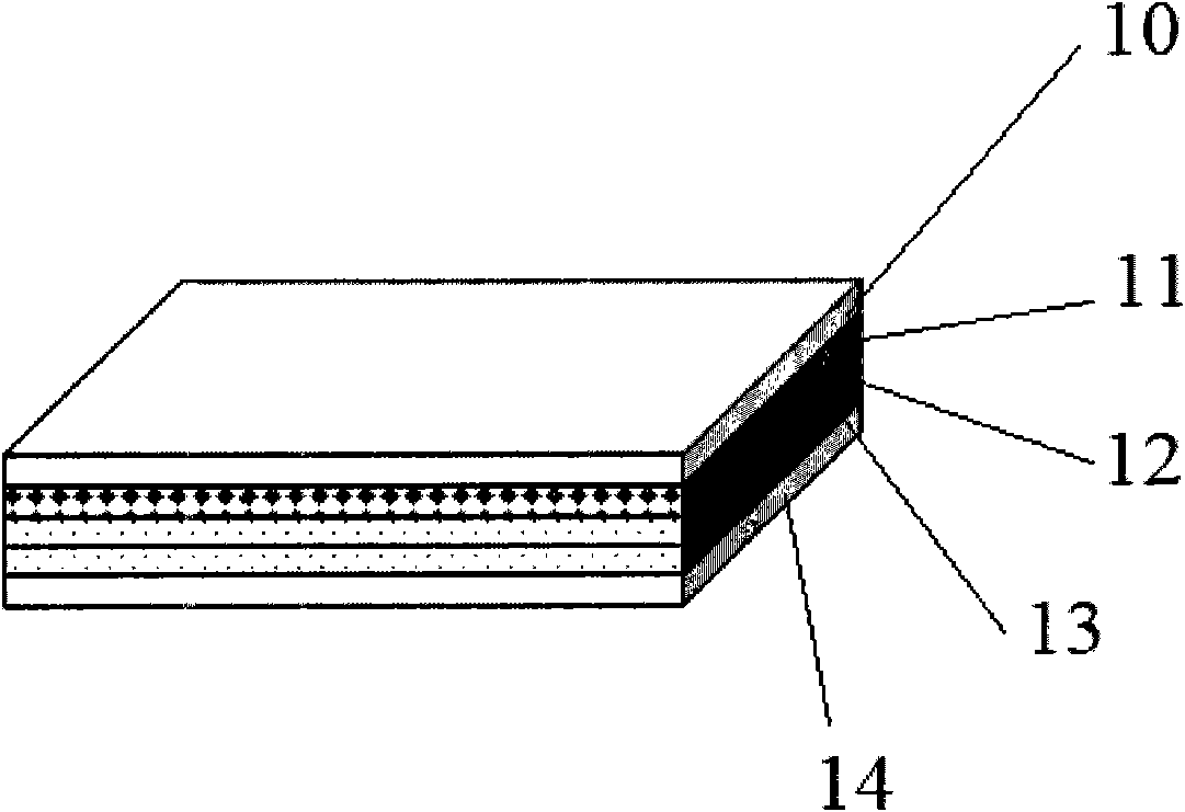
[0023] Such as figure 1 Shown is a schematic structural diagram of a dye-sensitized solar cell according to an embodiment of the present invention. Wherein the dye-sensitized solar cell includes a flexible polymer transparent conductive film ITO / PET10, the transparent conductive film is an oxide semiconductor indium tin oxide; the counter electrode platinum film 13 can be sputtered on the flexible polymer transparent conductive film ITO / PET prepared by the method; electrolyte 12, which contains I3- / I- ion pair; also includes TiO soaked dye 2 Thin film 11, the preparation method of this layer is as follows:

[0024] A certain amount of n-butyl titanate was slowly added d...


PUM


Abstract

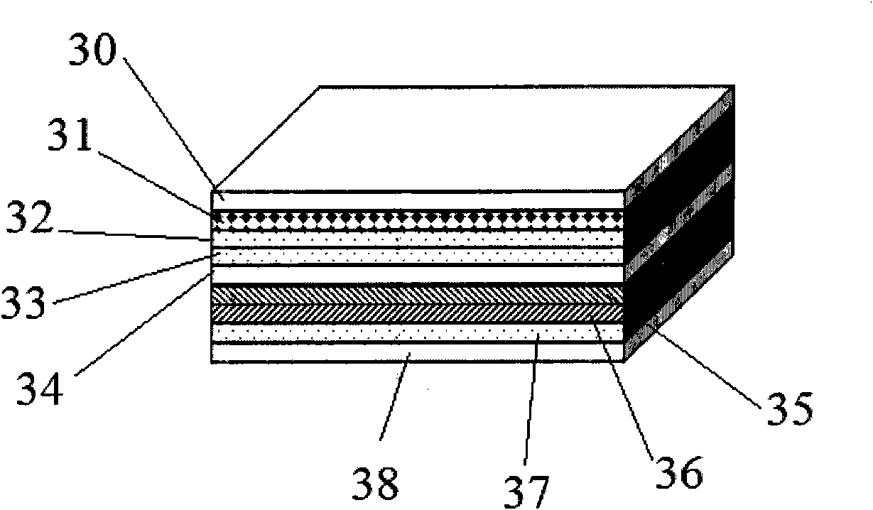
The invention discloses a laminated composite solar battery which comprises a polymer solar battery and a dye-sensitized solar battery formed on the polymer solar battery. Compared with the single dye-sensitized solar battery and the polymer solar battery, the composite solar battery enhances light absorption efficiency on the basis of basically maintaining the efficiencies of the two batteries, thereby enhancing photoelectric conversion efficiency.

Description

technical field [0001] The invention relates to the field of photovoltaic utilization of solar energy, in particular to a composite solar cell with a laminated structure of a polymer solar cell and a dye-sensitized solar cell. Background technique [0002] French scientist Henri Becqμerel first observed the phenomenon of photoelectric conversion in 1839, but it was not until the advent of the first practical semiconductor solar cell in 1954 that the idea of ​​"converting solar energy into electrical energy" really became a reality. Although the conversion efficiency of photovoltaic cells that directly utilize the photovoltaic effect to solar energy is several orders of magnitude higher than that of other indirect conversion methods, the installed capacity of photovoltaic cells worldwide is very limited. The main reason is that the existing inorganic silicon-based or Semiconductor photovoltaic cells are prohibitively expensive. Although its price has dropped a lot after deca...

Claims


Application Information

Patent Timeline
Patent Type & Authority Applications(China)
IPC IPC(8): H01L27/30H01L51/42H01G9/20H01M14/00
CPCY02E10/542Y02E10/549
Inventor 康晋锋张天舒范志伟王旭王宝王琰刘力锋
Owner PEKING UNIV
Learn More