Energy-saving steaming and boiling system

A cooking pot and heat exchange chamber technology, which is applied in the boiler technology and food processing equipment field, can solve the problems of energy saving and consumption reduction and the incompatibility of meeting process requirements, scorched pot, dry pot, burner, incomplete combustion of gas, etc. Achieve the effects of improving heat absorption and utilization efficiency, reducing exhaust emissions, and reducing energy consumption

Active Publication Date: 2012-07-11
四川华宇瑞得科技有限公司
View PDF5 Cites 8 Cited by
  • Summary
  • Abstract
  • Description
  • Claims
  • Application Information

AI Technical Summary

Problems solved by technology

However, the current gas direct combustion heating method is the traditional combustion flame heating the bottom of the pot for heat exchange. Due to the limitation of the appearance and shape of the bottom pot and the use environment, it is not compatible with energy saving and meeting the process requirements, and it is easy to Phenomena such as scorched pot, dry pot, burnt pan, etc.
[0003] In order to improve the energy-saving effect, the commonly used method is to install a heat exchange flue on the retort to prolong the heat exchange time of the gas and improve the heat exchange efficiency, such as Chinese patent 97244845.4, which is named "returning type wine retort" and 200420060888.X , the name is "wine pot", but these structures still have the disadvantages of incomplete combustion of gas and insufficient heat exchange, resulting in waste, and the general gas consumption is 900M 3 / T

Method used


Image

  • Energy-saving steaming and boiling system
  • Energy-saving steaming and boiling system
  • Energy-saving steaming and boiling system

Examples


Embodiment Construction

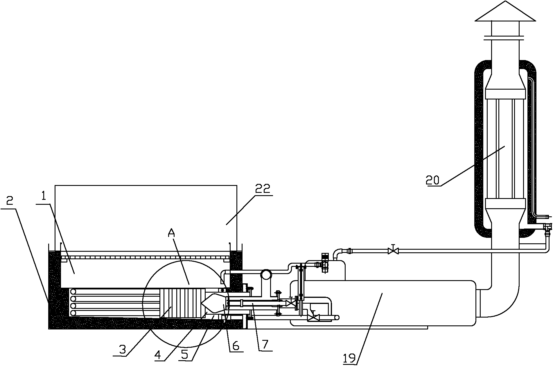
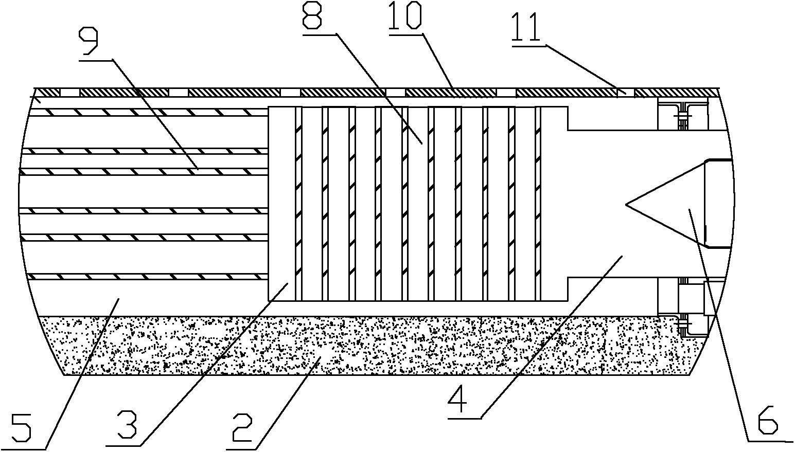
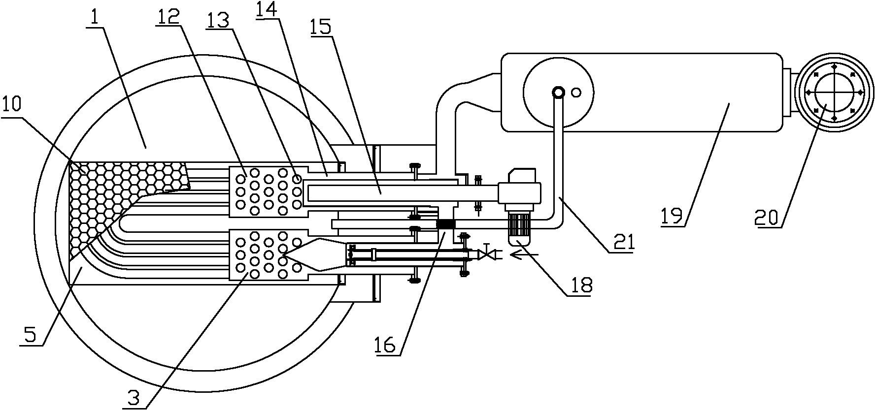
[0020] The energy-saving cooking system of the present invention includes a cooking pot 1 containing heated water for generating steam and a combustion chamber 4 below it for heating. A heat exchange tank 5 is installed below the cooking pot 1 , the inner chamber of the water exchange tank 5 communicates with the inside of the cooking pot 21 , and the heating water between them can flow mutually. The above-mentioned heat exchange tank 5 is provided with a high-temperature heat exchange chamber 3, and the inner cavity of the high-temperature heat exchange chamber 3 and the inner cavity of the water exchange tank 5 are in a closed structure, that is, the surrounding walls of the high-temperature heat exchange chamber 3 are all immersed in the water exchange tank. 5, while ensuring that the heating water in the heat exchange tank 5 cannot enter the inner cavity of the high-temperature heat exchange chamber 3. The inner cavity of the high-temperature heat exchange chamber 3 commun...


PUM


Abstract

The invention discloses a steaming and boiling system, which is particularly suitable for boiling water at a pot bottom to generate steam during a food steaming and boiling heat process. The invention provides an energy-saving steaming and boiling system capable of increasing the heat exchange area and improving the heat utilization efficiency. The energy-saving steaming and boiling system comprises a steaming and boiling pot and a combustion chamber arranged below the steaming and boiling pot, wherein a heat exchange water tank is mounted below the steaming and boiling pot, and an inner cavity of the heat exchange water tank is communicated with the inside of the steaming and boiling pot; a high-temperature heat exchange chamber is arranged in the heat exchange water tank, and a closed structure is formed between an inner cavity of the high-temperature heat exchange chamber and the inner cavity of the heat exchange water tank; the inner cavity of the high-temperature heat exchange chamber is communicated with the combustion chamber; a smoke outlet is further arranged on the high-temperature heat exchange chamber; high-temperature heat exchange tubes are mounted and configured in the high-temperature heat exchange chamber, vertically penetrate upper and lower walls of the high-temperature heat exchange chamber, and are communicated with the inner cavity of the heat exchange water tank; and a combustion engine is mounted in the combustion chamber, and the high-temperature heat exchange tubes are mounted in front of a burner of the combustion engine. The energy-saving steaming and boiling system can reduce energy consumption, decrease exhaust emission and lower production cost.

Description

technical field [0001] The invention relates to the fields of boiler technology and food processing equipment, in particular to a cooking system suitable for boiling bottom pot water or making bottom pot water generate steam during the cooking and heating process of food. Background technique [0002] Currently, in the liquor brewing process, the fermented distiller's grains are distilled to get the wine. The main heating methods of most of the liquor brewing enterprises now include centralized steam heating and gas fuel to carry out controllable direct-fired heating for each wine retort. In comparison, the way of direct combustion heating is more energy-saving and easy to control, which is the current development direction of liquor production. However, the current gas direct combustion heating method is the traditional combustion flame heating the bottom of the pot for heat exchange. Due to the limitation of the appearance and shape of the bottom pot and the use environme...

Claims


Application Information

Patent Timeline
Patent Type & Authority Applications(China)
IPC IPC(8): C12G3/00A23L1/01A23L5/10
CPCY02P60/80
Inventor 魏华海廖泽刚魏先勇范润黎
Owner 四川华宇瑞得科技有限公司
Why Eureka
Try Eureka