
High-temperature synthesis gas sensible heat recovery device

A technology of sensible heat recovery and synthesis gas, which is applied in the directions of joint combustion mitigation, production of combustible gas, and climate sustainability. The device is simple and compact, the investment is low, and the operation is reliable.

Active Publication Date: 2010-07-21
SHANGHAI BOILER WORKS +2
View PDF1 Cites 22 Cited by
  • Summary
  • Abstract
  • Description
  • Claims
  • Application Information

AI Technical Summary

Problems solved by technology

[0004] Since 2001, domestic enterprises have successively introduced 23 Shell coal gasification units. At present, only half of the gasifiers are in trial run or start-up operation, and the operating conditions have not met expectations. The main reason is that molten ash accumulates in the gasifier slag pool. Large slag blocks block the slag outlet of the slag pool, seriously affecting the long-term operation of the gasification device; due to the ash accumulation in the convection boiler, which affects the heat transfer effect of the convection boiler, it is necessary to add about 2 / 3 of the designed chilling gas volume.
Shell pulverized coal gasification technology uses a large amount of circulating syngas to quench the high-temperature syngas, which increases the size of the convection boiler and its subsequent syngas dust removal equipment, and increases equipment investment. Syngas cycle compression increases the energy consumption of the gasification unit
[0005] The third technology is to use water quenching to cool the high-temperature synthesis gas at the outlet of the entrained bed gasifier, such as the quenching process of multi-nozzle opposed coal-water slurry gasification technology, and the quenching process of GE (formerly Texaco) coal-water slurry gasification technology. In the cold process, the steam generated is contained in the synthesis gas. This scheme is followed by a transformation process after the gasification unit to adjust CO, H 2 The proportioner is suitable, but it is not suitable for IGCC power generation and sponge iron production

Method used

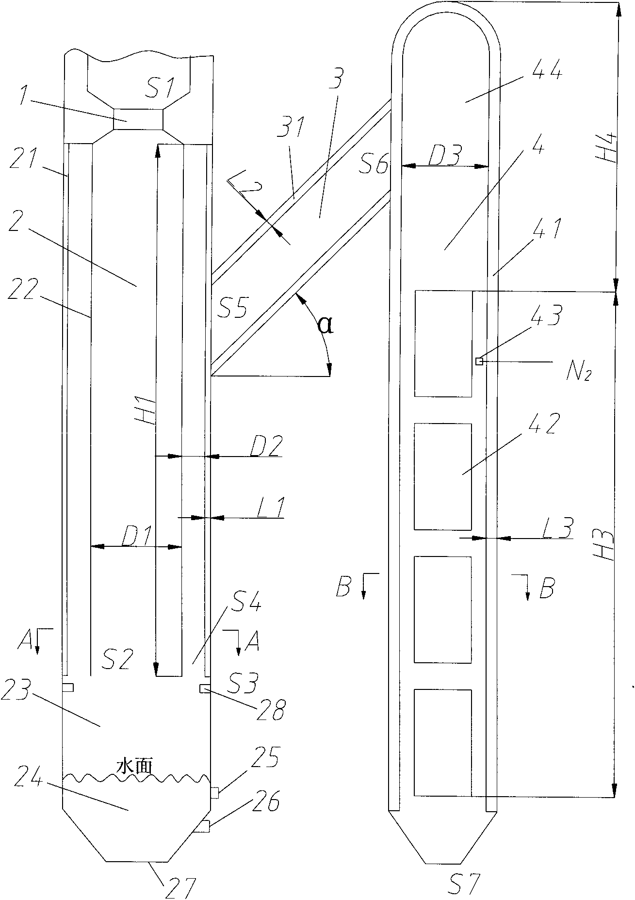
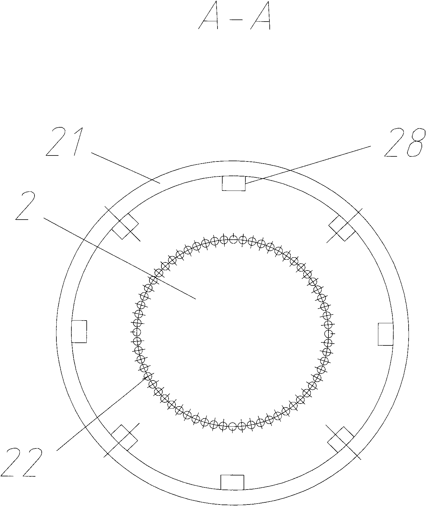
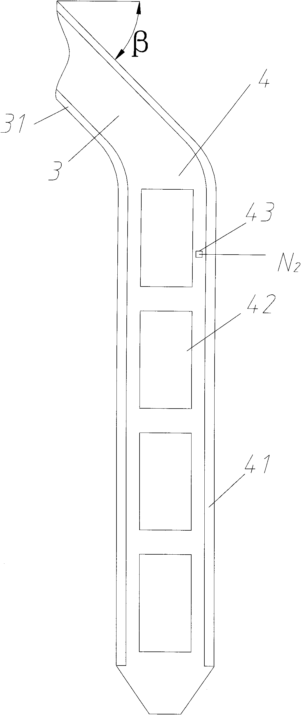

Image

  • High-temperature synthesis gas sensible heat recovery device
  • High-temperature synthesis gas sensible heat recovery device
  • High-temperature synthesis gas sensible heat recovery device

Examples


Embodiment

[0044] A pulverized coal fed entrained gasifier with a daily processing capacity of 2,000 tons of coal, the operating pressure is 4.0 MPa, and the operating temperature is 1,500°C. The characteristic data of the coal used are:

[0045] Industrial Analysis:

[0046] Received base moisture Mar 14% (wt);

[0047] Received base volatile Var 36.49% (wt)

[0048] Received base ash Aar 12% (wt)

[0049] Elemental analysis:

[0050] Received base carbon Car 61.45% (wt)

[0051] Received base hydrogen Har 3.61% (wt)

[0052] Received base oxygen Oar 7.80% (wt)

[0053] Received base nitrogen Nar 0.71% (wt)

[0054] Received base total sulfur St, ar 0.43% (wt)

[0055] Calorific value:

[0056] Received base low calorific value Qnet, ar 23420kJ / kg

[0057] Ash melting point:

[0058] Flow temperature FT 1350°C

[0059] The process data of the syngas outlet of the gasifier and the sensible heat recovery device of the high-temperature syngas are shown in Table 1:

[0060] Tabl...


PUM


Abstract

The invention relates to a high-temperature synthesis gas sensible heat recovery device which is characterized by comprising a radiation boiler, wherein the radiation boiler is connected with a convection boiler by a synthesis gas pipe. The invention recovers the sensible heat of the high-temperature synthesis gas from an entrained flow gasifier by using a radiation type steam generator, a gas quenching step and a convection type steam generator to generate medium-pressure or high-pressure steam, thereby increasing the thermal efficiency for the gasification of the entrained flow by more than10-15%. The device is concise and compact, has reliable operation and low investment, is a high-efficiency and energy-saving device, and can be widely used in the fields of integral gasification combination cycle power generation (IGCC), methanol and alkene production, coal-to-liquid, spongy iron production by the synthesis gas direct reduction iron-making method and the like.

Description

technical field [0001] The invention relates to a heat recovery device connected with an entrained-bed gasification furnace, which can be used for sensible heat recovery of high-temperature syngas from various entrained-bed gasification furnaces fed in slurry or powder state, with a by-product of 1.0-15.0 MPa Steam, used in integrated gasification combined cycle power generation (IGCC), methanol and olefin production, coal-to-oil, synthesis gas direct reduction ironmaking to produce sponge iron and other fields. Background technique [0002] At present, all countries in the world are paying great attention to the efficient and clean utilization of energy. The high-temperature syngas exiting the entrained bed gasifier has a very high enthalpy value. There are currently three schools of thought in the world on how to effectively utilize it. The first is representative of GE (formerly Texaco), the IGCC power station (Tampa Electric Integrated Gasification Combined-Cycle Projec...

Claims


Application Information

Patent Timeline
IPC IPC(8): C10J3/86
CPCY02E20/18Y02E20/16Y02P20/10
Inventor 杨震郭琴琴刘建斌梁新忠龚欣刘海峰代正华于广锁梁钦锋许建良亢万忠郭文元章晨晖李晓黎周洪义
Owner SHANGHAI BOILER WORKS
Learn More