
Ultrahigh temperature heating furnace

A heating furnace and ultra-high temperature technology, used in lighting and heating equipment, furnaces, muffle furnaces, etc., can solve the problems of polluting the sintered material, unable to meet the needs of scientific research institutes and scientific and technological development, and staying in the laboratory.

Inactive Publication Date: 2010-07-28
LUOYANG SIGMA FURNACE
View PDF7 Cites 13 Cited by
  • Summary
  • Abstract
  • Description
  • Claims
  • Application Information

AI Technical Summary

Problems solved by technology

The maximum surface temperature of the lanthanum chromate heating element is 1900°C, and the operating temperature in the furnace is 1800°C; the disadvantage of this element is that when it is used under high temperature conditions, the lanthanum chromate volatilizes to produce a chromium oxide substance, which often contaminates the sintered object , limiting the use of the component
The maximum surface temperature of the zirconia heating element is 2100°C, and the operating temperature in the furnace is 2000°C; the disadvantage of this element is that at low temperatures, zirconia does not conduct electricity, and when using this element, an auxiliary heating system must be used to convert the zirconia Zirconium is heated above 1100°C. When making a furnace, the heating elements of the auxiliary heating system cannot withstand the high temperature of 2000°C. The manufacturing process and the requirements for the furnace material are particularly high. So far, no durable ultra-high temperature electric furnace has been produced. Just stay in the laboratory stage
[0003] Therefore, the ultra-high temperature electric furnaces used in the oxidizing atmosphere environment and ultra-high temperature conditions are far from meeting the needs of scientific research institutes and technological development due to the defects of the heating elements used.

Method used


Image

  • Ultrahigh temperature heating furnace
  • Ultrahigh temperature heating furnace
  • Ultrahigh temperature heating furnace

Examples


Embodiment 1

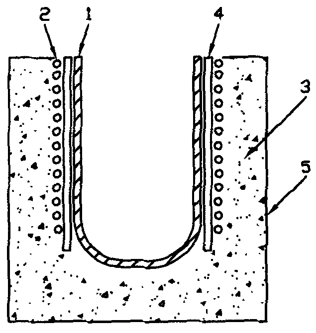
[0022] Embodiment 1: An induction oxidation furnace, also called an induction melting furnace, includes a transformer, a furnace body 5 , a controller, and an insulating material 3 and an insulating material 4 . Induction oxidation furnace of the present invention is first to ZrB 2 The composite ceramic material is made into a zirconium diboride composite ceramic hearth 1, and an induction coil 2 or a copper tube is arranged around a circular hearth to make an inductor. In this embodiment, an induction coil is used. by ZrB 2 The circular hearth made of composite ceramic material is heated by induction, and the sintered object is placed in the hearth for oxidation, with the mouth of the hearth facing up and the bottom of the hearth facing down.

Embodiment 2

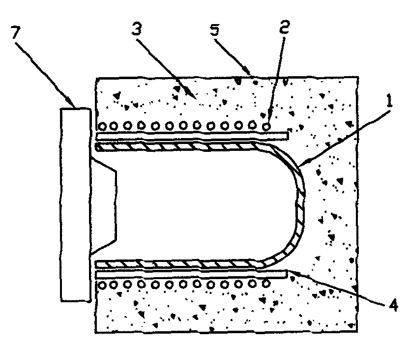
[0023] Embodiment 2: It includes a transformer, a furnace body 5 , a controller, an insulating material 3 and an insulating material 4 . The high-temperature furnace described in this embodiment is first to put ZrB 2 The composite ceramic material is made into a circular or square zirconium diboride composite ceramic hearth 16, which is arc-shaped in this embodiment, and the winding induction coil 2 is made into an inductor, and the ZrB 2 The circular or square furnace made of composite ceramic materials is heated by induction. The sintered object is placed in the furnace for sintering, annealing, etc., the furnace is placed flat, the mouth of the furnace faces forward, and the bottom of the furnace faces backward. A furnace door7.

Embodiment 3

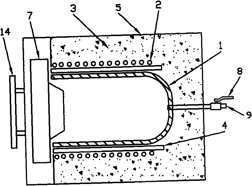
[0024] Embodiment 3: An induction vacuum furnace, also called an induction melting furnace, includes a transformer, a furnace body 5 , a controller, an insulating material 3 , and an insulating material 4 . The induction vacuum furnace of the present embodiment is at first ZrB 2 Composite ceramic materials are used as zirconium diboride composite ceramic hearth 16, and induction coil 2 is arranged around the circular hearth to make an inductor. 2 The circular hearth made of composite ceramic materials is heated by induction. The sintered object is placed in the hearth for sintering, annealing, etc. The hearth is placed flat, the mouth of the hearth faces forward, and the bottom of the hearth faces backward. Door 7, a sealing flange 14 is arranged outside the furnace door 7, such a body of furnace is arranged in a closed metal box, the furnace is connected to a vacuum pump through a pipeline, and a valve 8 and an air extraction port 9 are arranged on the pipeline. Vacuum sinte...


PUM


Abstract

The invention discloses an ultrahigh temperature heating furnace which comprises a transformer, a controller, a furnace body, an inductor, a heat-preserving insulating material, a hearth, an infrared thermometer and a circulating water cooling device, wherein the heat-preserving insulating material is arranged in the furnace body, the infrared thermometer is arranged at one side of the furnace body, the transformer, the controller and the inductor are cooled through circulating water, the hearth is made of a zirconium diboride composite ceramic material, the inductor is positioned at the periphery of the hearth, and the heat-preserving insulating material is arranged between the inductor and the hearth. In the invention, when an alternating current power supply is input into an induction coil, an alternating electromagnetic field is formed in the inductor mainly through an induction heating principle. When the magnetic flux of the alternating electromagnetic field passes through the hearth made of the ZrB2 composite ceramic material, an eddy current can be generated, a large amount of heat can be generated by the hearth made of the ZrB2 composite ceramic material, and the hearth can heat. A high temperature environment is formed in the hearth and used for sintering under an oxidizing atmosphere and a vacuum atmosphere.

Description

technical field [0001] The invention belongs to an ultra-high temperature induction heating furnace, and mainly relates to a furnace using zirconium diboride (ZrB 2 ) Ultra-high temperature heating furnace made of composite ceramic materials. Background technique [0002] The heating furnace over 1800°C in the furnace becomes an ultra-high temperature heating furnace. The usual ultra-high temperature resistance furnace uses heating elements in an oxidizing atmosphere, and only lanthanum chromate heating elements and zirconia heating elements are used. The maximum surface temperature of the lanthanum chromate heating element is 1900°C, and the operating temperature in the furnace is 1800°C; the disadvantage of this element is that when it is used under high temperature conditions, the lanthanum chromate volatilizes to produce a chromium oxide substance, which often contaminates the sintered object , limiting the use of this component. The maximum surface temperature of the...

Claims


Application Information

Patent Timeline
IPC IPC(8): F27B5/00F27B5/05F27B5/06F27B5/16F27B5/18
Inventor 周森安郑传涛李小华任飞雷
Owner LUOYANG SIGMA FURNACE
Learn More