Heating-furnace cogeneration system and method thereof

A technology of waste heat power generation and heating furnace, which is applied in the waste heat power generation system of heating furnace and the waste heat power generation of steel rolling heating furnace in steel mills. Efficiency, the effect of ensuring stable operation

Active Publication Date: 2010-07-28
SHOUGANG CORPORATION
View PDF0 Cites 13 Cited by
  • Summary
  • Abstract
  • Description
  • Claims
  • Application Information

AI Technical Summary

Problems solved by technology

[0005] The purpose of the present invention is to provide a heating furnace waste heat power generation system and its method. Firstly, through the configuration of the superheated steam boiler combustion system, the superheated steam boiler can still ensure the low load and stable operation of the waste heat power generation system when the heating furnace is waiting to be rolled. It solves the problem that the waste heat power generation system cannot run continuously due to the discontinuous production of the heating furnace when it is waiting for rolling; secondly, the steam parameters of the waste heat power generation equipment of the heating furnace are improved by using the superheated steam boiler, and the power generation efficiency is improved; finally, the waste heat of the heating furnace is improved by the present invention. Maximum recovery, good economic and environmental benefits, and good application and promotion value
Recover the waste heat of the flue gas of the heating furnace as much as possible; improve the efficiency of waste heat power generation as much as possible; solve the contradiction between the heating furnace waiting for rolling and the continuous operation of the heating furnace waste heat power generation system

Method used


Image

  • Heating-furnace cogeneration system and method thereof
  • Heating-furnace cogeneration system and method thereof

Examples


Embodiment Construction

[0024] The present invention will be further described below in conjunction with the drawings.

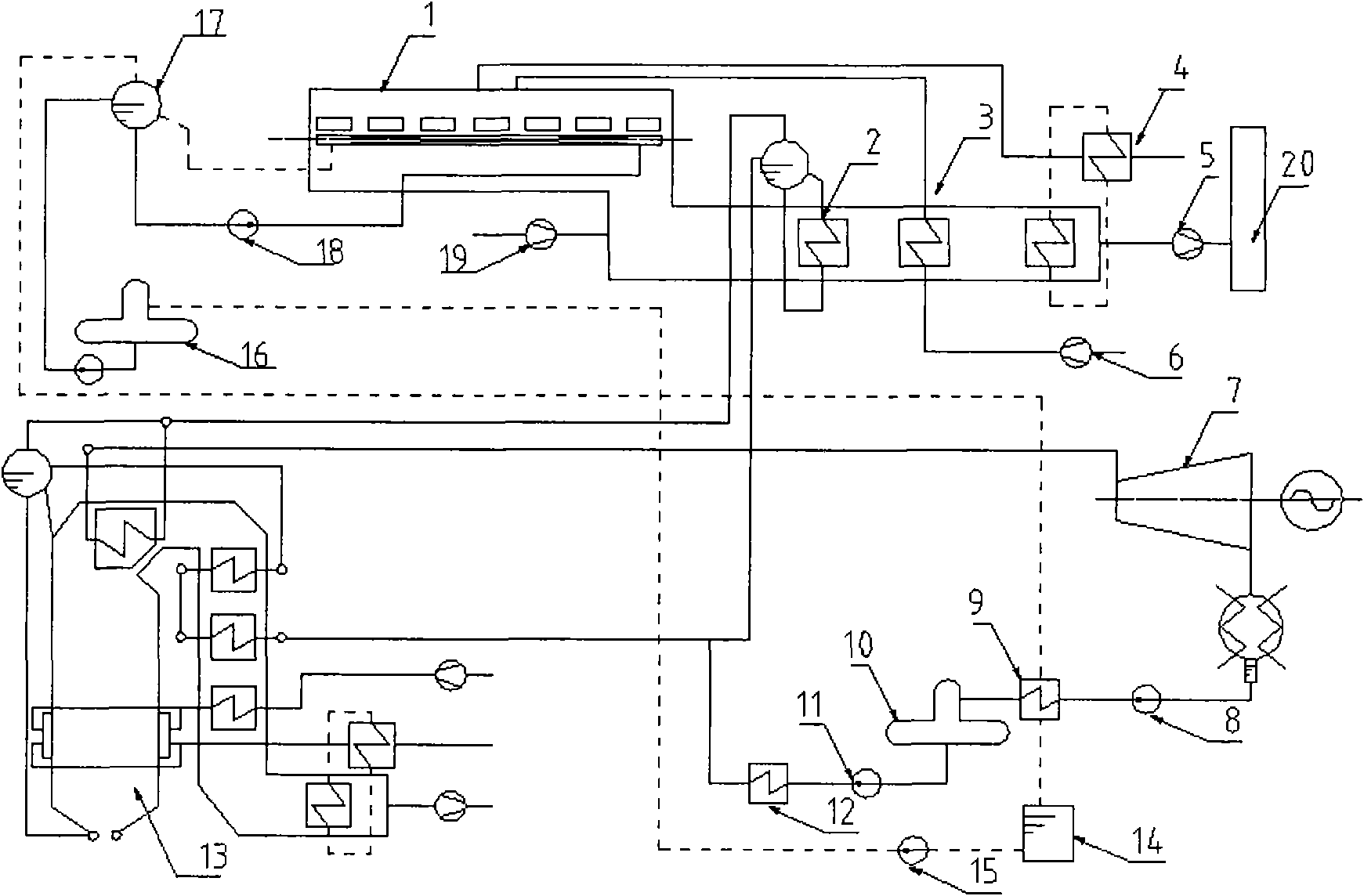
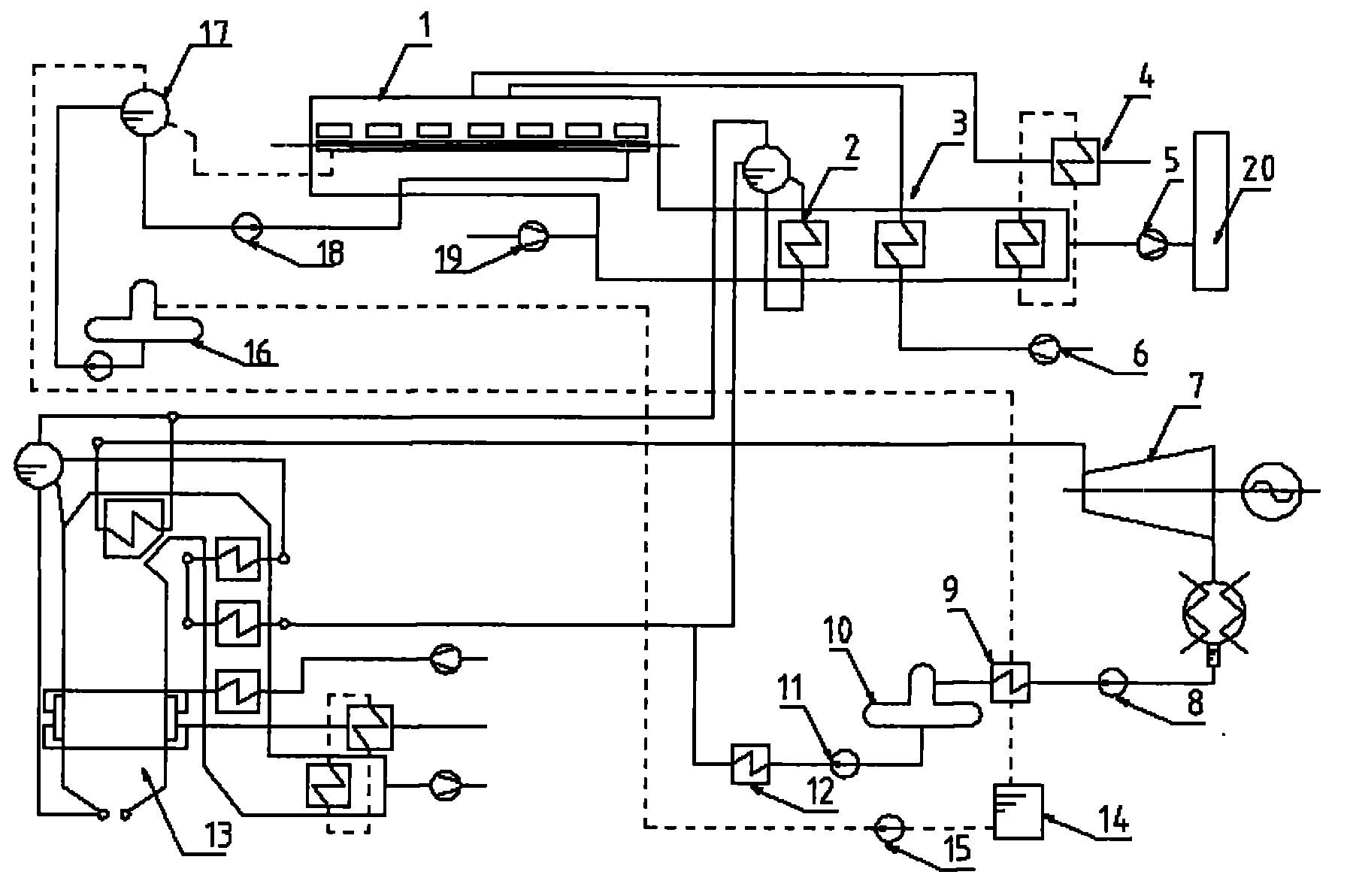
[0025] The system of the present invention includes a heating furnace 1, a heating furnace waste heat boiler 2, a heating furnace air preheater 3, a heating furnace heat pipe gas preheater 4, a heating furnace tail suction fan 5, a superheated steam boiler 13, and a steam turbine generator set 7. , Chemical water system, etc. The present invention arranges the heating furnace waste heat boiler 2, the heating furnace air preheater 3, the heating furnace heat pipe gas preheater 4, and the heating furnace tail suction fan 5 in sequence along the flue gas flow at the tail of the heating furnace 1 to fully recover the heating furnace smoke Gas waste heat. The saturated steam produced by the waste heat boiler 2 of the heating furnace enters the superheated steam boiler 13 to further increase the temperature, and then enters the turbine generator set 7 for power generation. The chemical wa...


PUM


Abstract

The invention relates to a heating-furnace cogeneration system and a method thereof, and belongs to the field of waste energy and heat recovery. The cogeneration system comprises a heating furnace, a heating-furnace waste heat boiler, a heating-furnace air preheater, a heating-furnace heat-pipe coal gas preheater, a heating-furnace tail suction fan, a superheated steam boiler, a turbogenerator set and a chemical water system, wherein the heating-furnace tail is orderly provided with the heating-furnace waste heat boiler, the heating-furnace air preheater, the heating-furnace heat-pipe coal gas preheater and the heating-furnace tail suction fan along the fume flow direction, and used for recovering the fume waste heat of the heating furnace; the heating-furnace waste heat boiler is used for generating electricity; and the chemical water system is used for providing supplementary water for the heating-furnace waste heat boiler and the superheated steam boiler. The invention enables the superheated steam boiler to still ensure the low-load stable operation of the cogeneration system when heating furnace is to be rolled, increases the steam parameter of the heating-furnace waste heat generating equipment by utilizing the superheated steam boiler, and enhances the generating efficiency. The invention maximally recovers the waste heat of the heating furnace, thereby having favorable economic and environmental benefits and high values for application and popularization.

Description

Technical field [0001] The invention belongs to the field of waste energy and waste heat recovery and utilization, in particular to a heating furnace waste heat power generation system and a method thereof, and is suitable for steel rolling heating furnace waste heat power generation in steel plants. Background technique [0002] Steel rolling heating furnaces in iron and steel enterprises, as large energy consumers, directly affect the production costs of enterprises. The thermal efficiency of a general heating furnace as a heating device is generally about 30%, high energy consumption and low energy utilization, resulting in a lot of energy waste. Therefore, recycling the waste heat of the heating furnace has both good economic benefits and certain environmental benefits. [0003] At present, most steel companies use vaporized cooling walking beam heating furnaces. The general fuel is mixed gas and the exhaust method is natural exhaust. The exhaust gas temperature of the prehea...

Claims


Application Information

Patent Timeline
Patent Type & Authority Applications(China)
IPC IPC(8): F27D17/00F01K11/02F01K17/02F01D15/10
CPCY02E20/14Y02P10/25Y02P80/15
Inventor 张效鹏汪洪涛张延平马泽军李国玮岳勇杨天助
Owner SHOUGANG CORPORATION
Why Eureka
Try Eureka