Variable band gap double-side transparent electrode thin film solar battery

A solar cell and transparent electrode technology, applied in circuits, photovoltaic power generation, electrical components, etc., can solve problems such as insufficient utilization of solar energy, and achieve the effect of increasing the effective power generation area, improving the photoelectric conversion efficiency, and increasing the utilization efficiency.

Inactive Publication Date: 2010-07-28
刘莹
View PDF4 Cites 11 Cited by
  • Summary
  • Abstract
  • Description
  • Claims
  • Application Information

AI Technical Summary

Problems solved by technology

These schemes can only receive sunlight on one side due to the opaque metal electrodes, and do not make full use of solar energy.

Method used


Image

  • Variable band gap double-side transparent electrode thin film solar battery
  • Variable band gap double-side transparent electrode thin film solar battery
  • Variable band gap double-side transparent electrode thin film solar battery

Examples


Embodiment 1

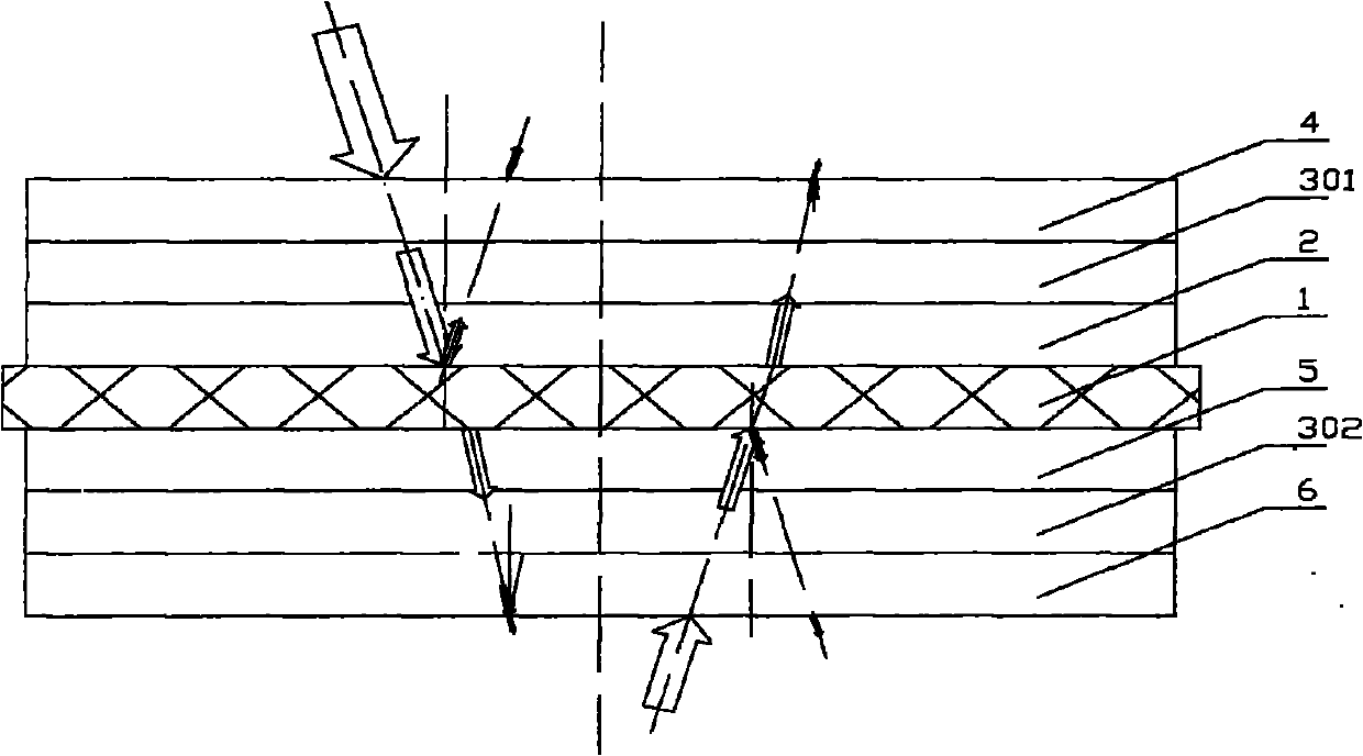
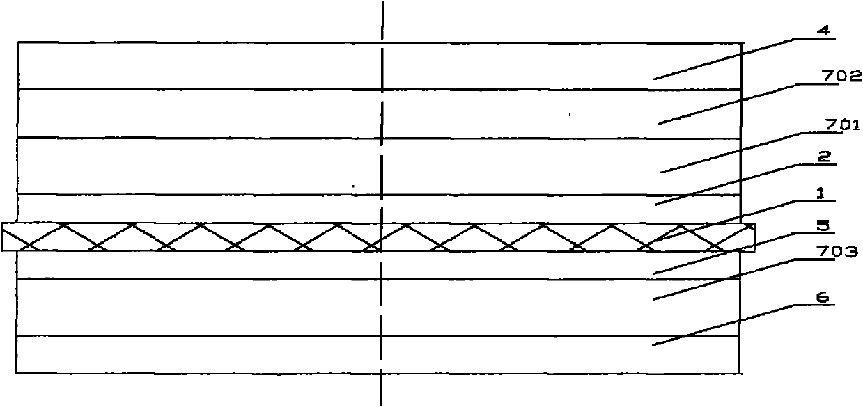
[0023] Such as figure 2 As shown, the present invention discloses a thin-film solar cell with variable bandgap double-sided transparent electrodes, comprising a transparent tempered glass substrate 1, a transparent conductive ITO film 2 is arranged on the substrate, and an amorphous germanium-silicon PIN junction is arranged on the transparent conductive ITO film 2. 701, an amorphous silicon PIN junction 702 is further provided, and a transparent conductive ITO film 4 is provided on the amorphous silicon PIN junction 702. The other side of the substrate is provided with a transparent electrode ITO film 5 , a photoelectric conversion unit microcrystalline silicon PIN junction 703 is provided under the transparent electrode ITO film 5 , and a transparent conductive ITO film 6 is provided under the photoelectric conversion unit microcrystalline silicon PIN junction 703 .

[0024] In this embodiment, the amorphous silicon PIN junction 702 has a band gap of 1.8 eV and mainly absor...

Embodiment 2

[0030] Such as image 3 As shown, the present invention discloses another thin-film solar cell with variable bandgap double-sided transparent electrodes. The bandgap of the CIGS layer is arranged in a curved gradient from top to bottom in the range of 1.7ev to 1.0ev. The bandgap near the transition layer is 1.7ev, and the bandgap near the substrate is 1.0ev. A ZAO transparent conductive electrode 4 is provided above the CIGS photoelectric conversion unit 801 . On the other side of the substrate, a transparent conductive electrode 5 is firstly arranged, and an amorphous mercury cadmium telluride photoelectric conversion unit 802 is arranged on the transparent conductive electrode 5, and its bandgap distribution is a curve in the range of 1.1ev to 0.13ev from near the substrate to the light-receiving surface. Gradient arrangement, ZAO transparent conductive electrode 6 is set on 802 again.

[0031] The two photoelectric conversion units used in this embodiment all have variabl...

Embodiment 3

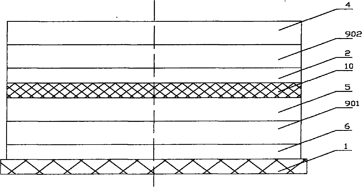
[0033] Such as Figure 4 As shown, the present invention discloses another kind of variable bandgap double-sided transparent electrode thin-film solar cell. Its structure is as follows. First, a transparent glass substrate 1 is arranged, and a first transparent conductive electrode 2 of ITO is arranged on the glass substrate. A microcrystalline silicon PIN junction 901 is arranged on the pole 2, a ZAO second transparent conductive electrode 4 is arranged on the microcrystalline silicon PIN junction 901, a transparent insulating layer 10 is arranged on the transparent conductive electrode, and a third ZAO transparent conductive electrode 5 is arranged on the insulating layer 10, An amorphous silicon PIN junction 902 is arranged on the transparent conductive electrode, and a ZAO fourth transparent conductive electrode 6 is arranged on the amorphous silicon PIN junction 902 .

[0034] In this embodiment, the transparent substrate is placed at the bottom of the solar cell, and the...


PUM


Abstract

The invention discloses a variable band gap double-side transparent electrode thin film solar battery which comprises a transparent substrate, wherein one side of the transparent substrate is provided with a first transparent conductive electrode; a photoelectric conversion unit 1 is arranged above the first transparent conductive electrode, and a second transparent conductive electrode is arranged above the photoelectric conversion unit 1; the other side of the substrate is provided with a third transparent conductive electrode; and a photoelectric conversion unit 2 is arranged on the third transparent conductive electrode, and a fourth transparent conductive electrode is arranged on the photoelectric conversion unit 2. The photoelectric conversion unit 1 and the photoelectric conversion unit 2 have different band gap distributions so as to correspond to different spectral response ranges and improve the photoelectric conversion efficiency. Meanwhile, due to the interaction of the upper photoelectric conversion unit and the lower photoelectric conversion unit, the conversion efficiency of the photoelectric conversion units is improved to a large extent. The invention ensures that the solar battery can accept light by double sides, thereby improving the light acceptance area of the solar battery in multiples. The structural change can ensure that the horizontal installation generating capacity of the solar battery is increased by 10 percent, and the vertical installation generating capacity is increased by 34 percent.

Description

technical field [0001] The invention relates to the field of thin-film solar cells, in particular to a thin-film solar cell with variable band gap double-sided transparent electrodes. Background technique [0002] Photovoltaic industry will hopefully solve our current energy and environmental problems. To achieve this goal, the requirement for solar power generation is grid parity. When it comes to the production of solar cells, lower costs and higher conversion efficiency are required. Thin-film solar cells have an advantage in the development of solar cells because of their lower cost. However, low conversion efficiency is still the main factor restricting their use as the main energy source for social development. [0003] In order to improve the conversion efficiency of thin-film solar cells, the industry has carried out a large number of technological innovations, such as the invention patent No. 200720172723.5 "A Stacked Solar Cell", by changing the traditional struc...

Claims


Application Information

Patent Timeline
Patent Type & Authority Applications(China)
IPC IPC(8): H01L31/042H01L31/0224
CPCY02E10/50
Inventor 刘莹
Owner 刘莹
Why Eureka
Try Eureka