
Magneto-rheological stepless speed changer

A continuously variable transmission and magneto-rheological technology, which is applied to friction transmission devices, belts/chains/gears, mechanical equipment, etc., can solve the problems of not considering the heat dissipation characteristics of the device, small transmission power, and reduced equipment volume, etc., to achieve wide practicality high performance, high power transmission and good heat dissipation

Inactive Publication Date: 2010-08-04
CHINA UNIV OF MINING & TECH +1
View PDF8 Cites 41 Cited by
  • Summary
  • Abstract
  • Description
  • Claims
  • Application Information

AI Technical Summary

Problems solved by technology

The above patents are all introductions to magnetorheological clutches and brakes. At present, there are few patents on magnetorheological continuously variable transmissions at home and abroad. CN1523251A discloses a magnetorheological continuously variable transmission with a V-shaped rotor structure, which adopts a double V-shaped structure. , the structure is simple, the transmission torque is small, and it is suitable for industrial low-power occasions, but it is not suitable for occasions that need to transmit high power. In addition, due to the small transmission power, the heat dissipation characteristics of the device are not considered; the brush mechanism is adopted. The coil can be rotated, reducing the size of the equipment, but the use of brushes is easy to generate electric sparks, which has limitations in coal mines and other occasions that require electric sparks

Method used


Image

  • Magneto-rheological stepless speed changer
  • Magneto-rheological stepless speed changer

Examples


Embodiment Construction

[0010] The present invention and an embodiment are further described below in conjunction with accompanying drawing:

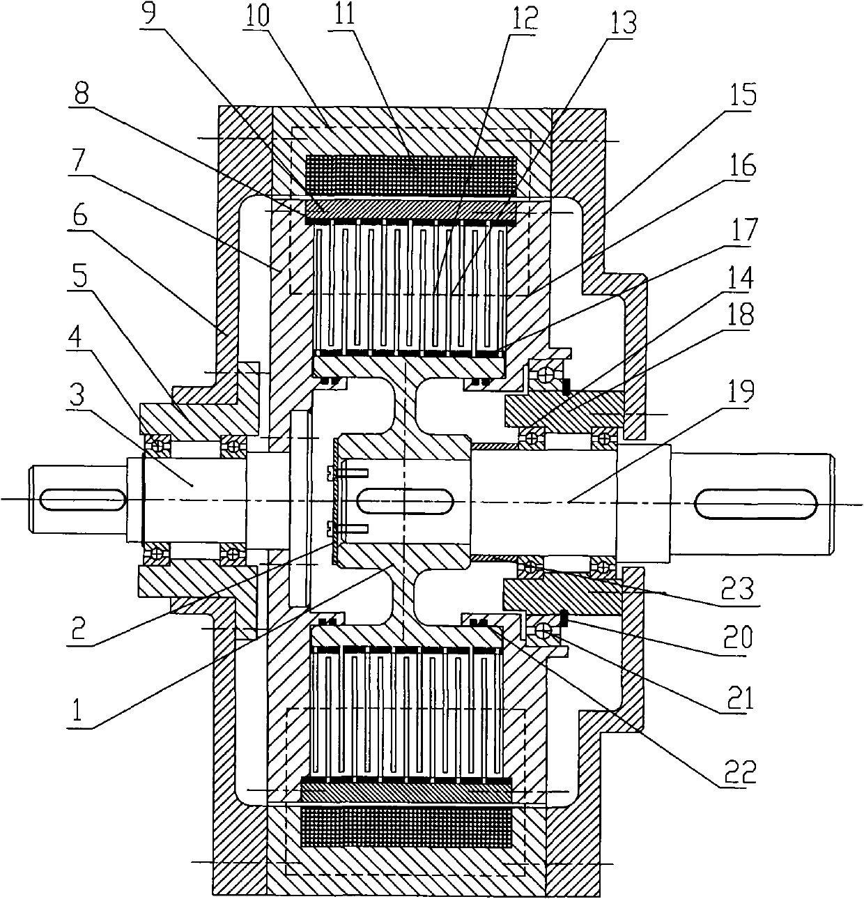
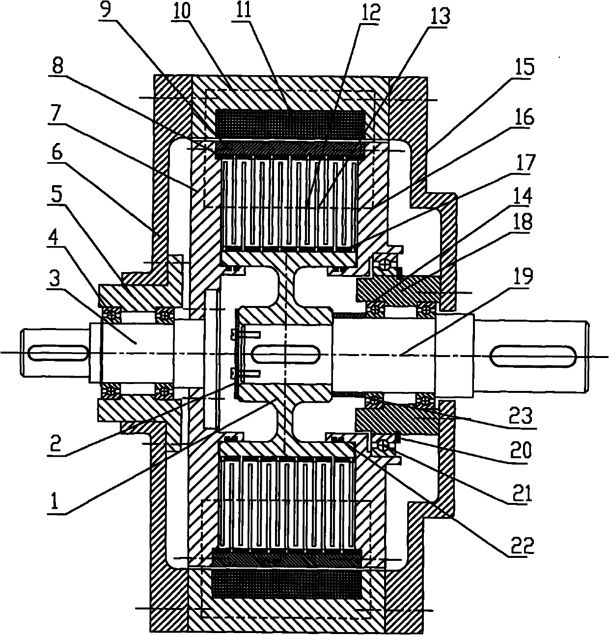
[0011] The magneto-rheological continuously variable transmission of the present invention mainly consists of a magnetic isolation hub 1, an input shaft 3, an output shaft 19, a driving friction plate 12, a driven friction plate 13, a bearing and a bearing seat, an excitation coil 11, a magnetic isolation ring, and a casing The box is composed of a magnetically permeable shell 10 with a groove inside, a left magnetically isolated side plate 6 and a right magnetically isolated side plate 15 arranged on both sides of the magnetically permeable shell 10 . The left magnetic isolation side plate 6 of the box body is fixedly connected with the left bearing seat 5 with built-in bearing 4, the left bearing seat 5 is provided with the input shaft 3, and the inner side of the right magnetic isolation side plate 15 of the box body is fixedly connected with the inner beari...


PUM


Abstract

The invention relates to a multi-disc type magneto-rheological stepless speed changer which mainly comprises a magnetic isolation hub, an input shaft, an output shaft, a driving friction plate, a driven friction plate, magnetic exciting coils and magnetic isolation rings; wherein the driving friction plate and the driven friction plate are respectively fixed on an outer magnetic isolation circular ring and the magnetic isolation hub through the magnetic isolation rings; a right magnetic conducting lateral plate is connected with the input shaft through a big magnetic isolation circular ring and a left magnetic conducting lateral plate; the output shaft is connected with the driven friction plate and the magnetic isolation hub; magneto-rheological fluid is sealed between the driving friction plate and the driven friction plate through a seal ring; the magnetic exciting coils are fixed on two bearing seats through a magnetic conducting shell, the left magnetic isolation lateral plate and the right magnetic isolation lateral plate in a motionless way, and the driving friction plate and the driving friction plate are in interleaved matching and isolated through the magnetic isolation rings. The shear yield stress of the magneto-rheological fluid can be changed by adjusting the electric current of the magnetic exciting coils, therefore, the speed difference between a driving shaft and a driven shaft is changed, and the stepless speed change is further realized. The invention has the advantages of simple structure, no electric sparks, high transmission torque and large transmission power.

Description

technical field [0001] The invention relates to a transmission, in particular to a magneto-rheological stepless transmission used for speed regulation of mechanical equipment with relatively large transmission torque. Background technique [0002] The traditional liquid viscous transmission is a fluid transmission technology that uses the shearing effect of the oil film to transmit torque. It is based on Newton's law of internal friction, and the transmission torque can be controlled by changing the thickness of the oil film. It is characterized by high speed regulation sensitivity and good stability, and the output speed can be adjusted steplessly within the range of 0-100%. However, it requires a huge oil supply system and complex control devices, which is bulky and expensive. [0003] Magnetorheological fluid is a smart material that can produce significant rheological properties under the action of a magnetic field. In the past ten years, due to its superior rheologica...

Claims


Application Information

Patent Timeline
IPC IPC(8): F16H15/01
Inventor 侯友夫田祖织
Owner CHINA UNIV OF MINING & TECH
Learn More