Multi-leg linear piezoelectric driver and workbench

A piezoelectric driver and driver technology, applied in the field of microelectronics, can solve problems such as inconvenient installation, insufficient thrust, and excessive temperature rise, and achieve the effects of convenient installation, increased driving force, and large contact area

Active Publication Date: 2010-08-04
TSINGHUA UNIV +2
View PDF4 Cites 28 Cited by
  • Summary
  • Abstract
  • Description
  • Claims
  • Application Information

AI Technical Summary

Problems solved by technology

[0004] The purpose of the present invention is to propose a multi-legged linear piezoelectric driver and workbench for the problems of insufficient thrust, too fast temperature rise and inconvenient installation of the existing driver.

Method used


Image

  • Multi-leg linear piezoelectric driver and workbench
  • Multi-leg linear piezoelectric driver and workbench
  • Multi-leg linear piezoelectric driver and workbench

Examples


Embodiment approach 1

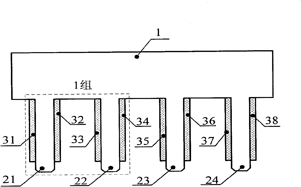
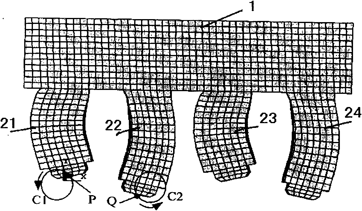
[0027] Such as figure 1 , 3 The structure of the multi-legged linear piezoelectric actuator shown in , 4 is comb-shaped, and a square first driving foot 21, a second driving foot 22, a third driving foot 23 and a fourth driving foot 24 are stretched out on the cuboid substrate 1 ; The number of driving feet is 4 and divided into two groups, and the two feet in each group are independent of each other. The square first piezoelectric ceramic sheet 31 and the second piezoelectric ceramic sheet 32 ​​are bonded on the side of the first driving foot 21, and the square third piezoelectric ceramic sheet 33 and the fourth piezoelectric ceramic sheet are bonded on the side of the second driving foot 22. Electric ceramic sheet 34; the fifth piezoelectric ceramic sheet 35 and the sixth piezoelectric ceramic sheet 36 are bonded on the side of the third driving foot 23; the seventh piezoelectric ceramic sheet is bonded on the side of the fourth driving foot 24 37 and the eighth piezoelect...

Embodiment approach 2

[0031] Such as Figure 4 As shown, the difference from the first embodiment is that the first driving foot 21 and the second driving foot 22 of the first group of the driver are connected by the first beam 401, and the third driving foot 23 and the fourth driving foot 24 of the second group are connected by The second beam 402 is connected; the side of the first beam 401 is pasted with the piezoelectric ceramic sheet 309 on the first beam and the piezoelectric ceramic sheet 310 under the first beam, and the side of the second beam 402 is pasted with the piezoelectric ceramic sheet on the second beam 311 and the piezoelectric ceramic sheet 312 under the second beam.

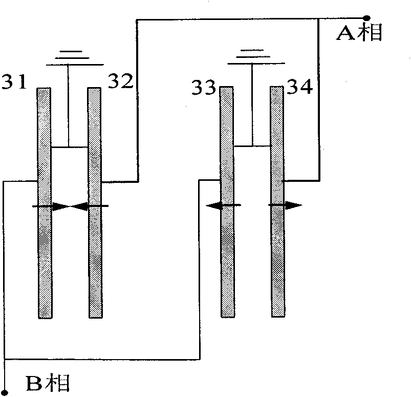
[0032] Such as Figure 5 As shown, the arrow indicates the polarization direction. In a group of driving feet, the polarization directions of the first piezoelectric ceramic sheet 31 and the second piezoelectric ceramic sheet 32 ​​on both sides of the first driving foot 21 are opposite to each other, and the sid...


PUM


Abstract

The invention belongs to a multi-leg linear piezoelectric driver and a workbench in the field of micro drivers. Diamond-shaped driving legs extending from a substrate of a piezoelectric driver form a comb-shaped structure, and square piezoelectric ceramic plates are bonded on the side surfaces of the driving legs, wherein the piezoelectric ceramic plates are polarized along the thickness direction of the piezoelectric ceramic plates, and the end faces of all the driving legs are on the same plane. Electrical signals are introduced to the electrode surfaces of the piezoelectric ceramic plates,the first-order stretching vibrations and the first-order or second-order bending vibrations of the driving legs can be simultaneously excited, and the coupling action of the two vibrations ensures that mass points on the bottom surfaces of the driving legs do elliptic motions and the elliptic vibrations of a plurality of leg bottoms of the driver are accumulated and superposed into a macroscopiclinear motion. The driver is arranged on a base of the workbench, and a grating bar and a grating head which are arranged on the base are used for providing a precise position of the workbench to realize the closed loop control of the workbench. Because the driver adopts a multi-leg driving mode, the driving force is increased in multiples; the contact areas of the piezoelectric ceramic plates with air are large so as to be beneficial to radiating heat; the assembly is convenient, and the cost is lower.

Description

technical field [0001] The invention belongs to the field of micro-driver in the field of microelectronic technology, and in particular relates to a multi-leg linear piezoelectric driver and a workbench which accumulate and superimpose the elliptical vibrations of multiple soles of the driver into macroscopic linear motion. Background technique [0002] The piezoelectric ultrasonic motor uses the inverse piezoelectric effect of piezoelectric ceramics to excite the ultrasonic vibration of the elastic body. Through structural design, the vibration is accumulated and superimposed into the macroscopic motion of the driving body. If the macro motion of the driver is rotary motion, it is called a rotary motor, and if the motion of the driving body is linear, it is called a linear motor. Piezoelectric ultrasonic motor has many advantages such as high precision, small inertia, fast response, self-locking when power off, high energy density, and no electromagnetic interference. So f...

Claims


Application Information

Patent Timeline
Patent Type & Authority Applications(China)
IPC IPC(8): H02N2/02
Inventor 褚祥诚袁松梅查海勇袁世明
Owner TSINGHUA UNIV
Why Eureka
Try Eureka