

Method for producing nanoparticles by forced ultra-thin film rotary processing
A nanoparticle and manufacturing method technology, applied in the directions of replication/marking methods, grain processing, chemical instruments and methods, etc., can solve problems such as difficulty in finding out the location of its failure, problem location, effective and suitable micro space, large liquid delivery pressure, etc.
- Summary
- Abstract
- Description
- Claims
- Application Information
AI Technical Summary
Problems solved by technology
Method used
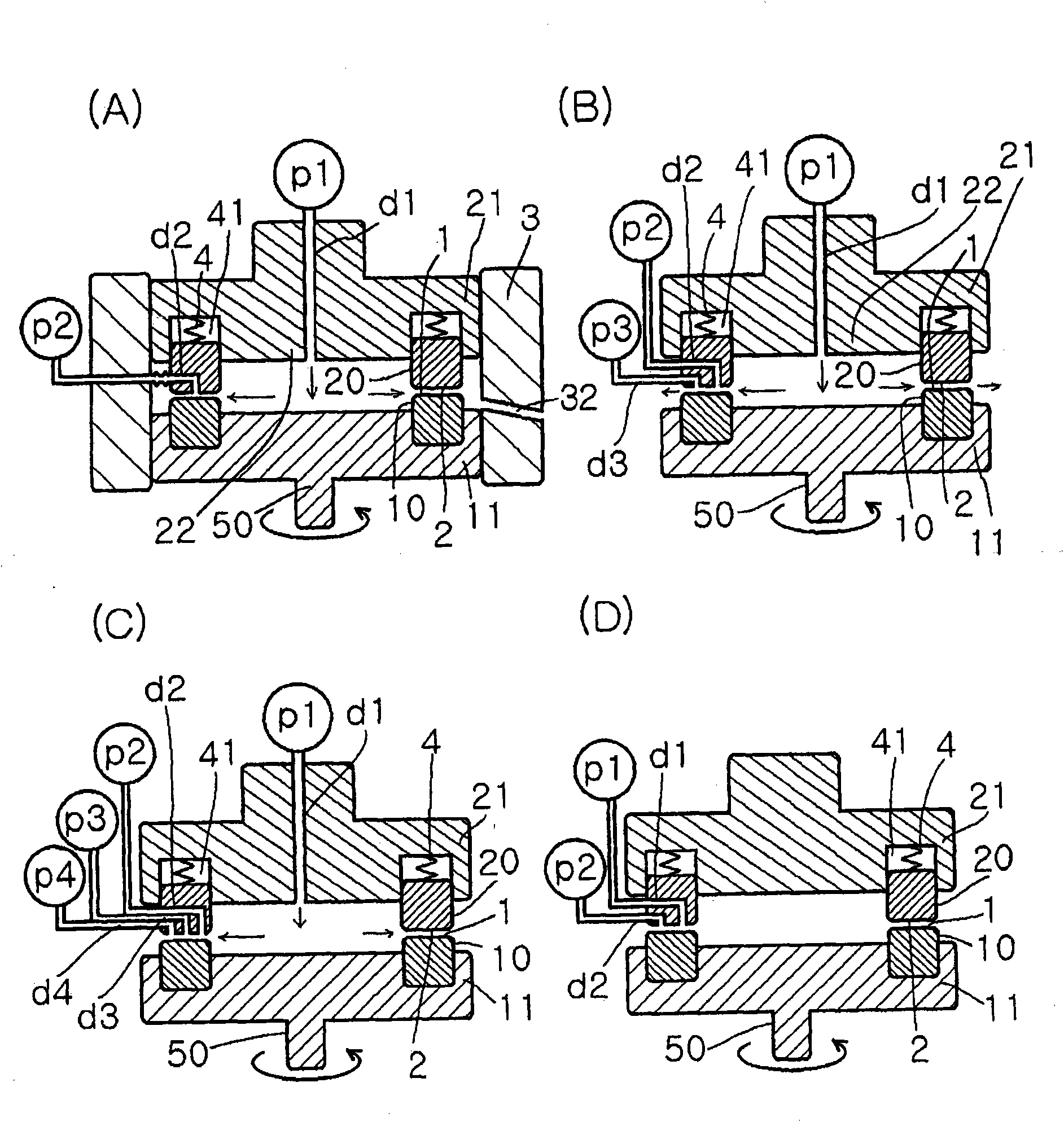
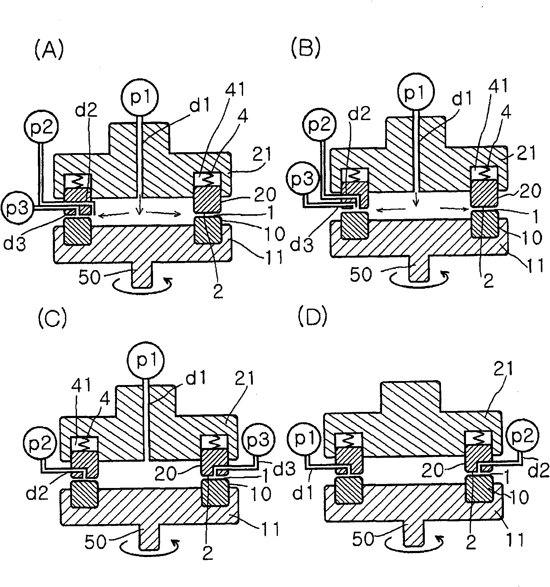
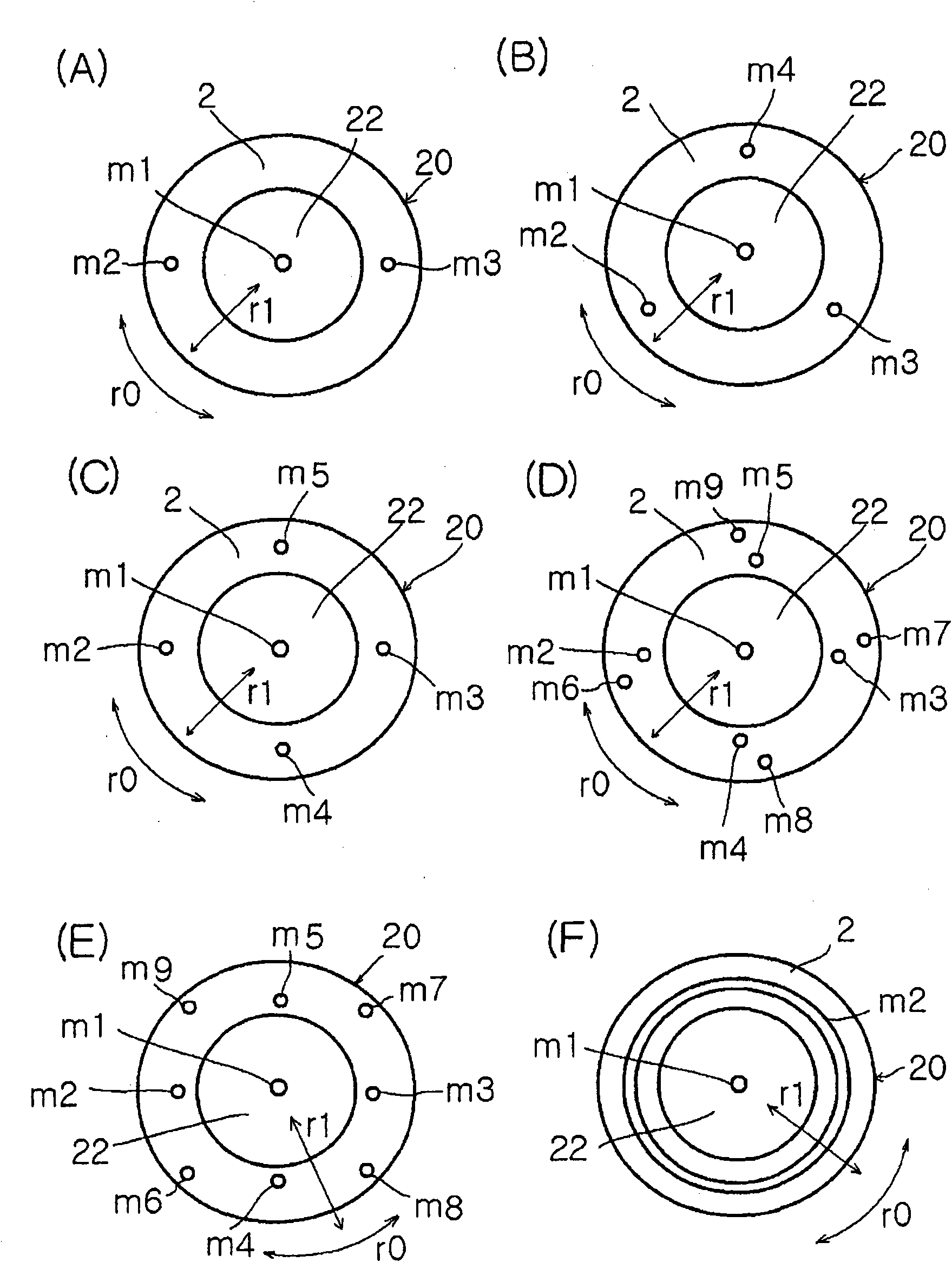
Image

Examples
Embodiment A1
[0461] While feeding Disper BYK 184 (manufactured by BYK Chemie) aqueous solution as the first fluid from the center at supply pressure / back pressure = 0.02MPa / 0.01Mpa, rotation speed 1000rpm, and liquid delivery temperature 20°C, the second fluid was A fluid 3% copper phthalocyanine pigment / 98% concentrated sulfuric acid aqueous solution was introduced between the processing surfaces 1 and 2 at a rate of 10 ml / min. The pigment nanoparticle dispersion liquid is discharged from the treatment surface. The particle size distribution of the obtained pigment nanoparticle dispersion liquid was measured using a particle size distribution measuring device (manufactured by Nikkiso Co., Ltd., trade name microtrac UPA150) using the laser Doppler method. As a result, the volume average particle diameter was 14 nm, and the particle size The CV value of the distribution is 13%. In addition, the pigment nanoparticle dispersion was dialyzed with pure water for 24 hours using a dialysis tube,...
Embodiment A2
[0463] While feeding Disper BYK 184 (manufactured by BYK Chemie) aqueous solution as the first fluid from the center at supply pressure / back pressure = 0.02MPa / 0.01Mpa, rotation speed 1000rpm, and liquid delivery temperature 20°C, the second fluid was The fluid 3% quinacridone pigment / 98% concentrated sulfuric acid aqueous solution was introduced between the processing surfaces 1 and 2 at 10 ml / min. The pigment nanoparticle dispersion liquid is discharged from the treatment surface. The particle size distribution of the obtained pigment nanoparticle dispersion liquid was measured using a particle size distribution measuring device (trade name microtrac UPA150 manufactured by Nikkiso Co., Ltd.) using the laser Doppler method. As a result, the volume average particle diameter was 15nm, the CV value of its particle size distribution is 14%. In addition, this pigment nanoparticle dispersion was dialyzed against pure water for 24 hours using a dialysis tube, and then dried to obta...
Embodiment A3
[0469] While sending ion-exchanged water as the first fluid from the center at supply pressure / back pressure = 0.01MPa / 0.01Mpa, rotation speed 1000rpm, and liquid delivery temperature of 25°C, 0.5% non-substituted straight water as the second fluid A chain quinacridone pigment / 1-methyl-2-pyrrolidone (NMP) solution was introduced between the processing surfaces 1 and 2 at 10 ml / min. The pigment nanoparticle dispersion liquid is discharged from the treatment surface. The particle size distribution of the obtained pigment nanoparticle dispersion liquid was measured using a particle size distribution measuring device (manufactured by Nikkiso Co., Ltd., microtrac UPA150) using the laser Doppler method. As a result, the volume average particle diameter was 18 nm. , the CV value of its particle size distribution is 17%. In addition, the pigment nanoparticle dispersion was dialyzed in pure water for 24 hours using a dialysis tube, and then dried to obtain a pigment nanoparticle powde...
PUM
| Property | Measurement | Unit |
|---|---|---|
| particle size | aaaaa | aaaaa |
| particle size | aaaaa | aaaaa |
| particle size | aaaaa | aaaaa |
Abstract
Description
Claims
Application Information