Direct type AC power converting device
A technology of power conversion device and DC power supply, which is applied in the direction of output power conversion device, AC motor control, and conversion of AC power input to AC power output. destroyed effect
- Summary
- Abstract
- Description
- Claims
- Application Information
AI Technical Summary
Problems solved by technology
Method used
Image
Examples
no. 1 approach
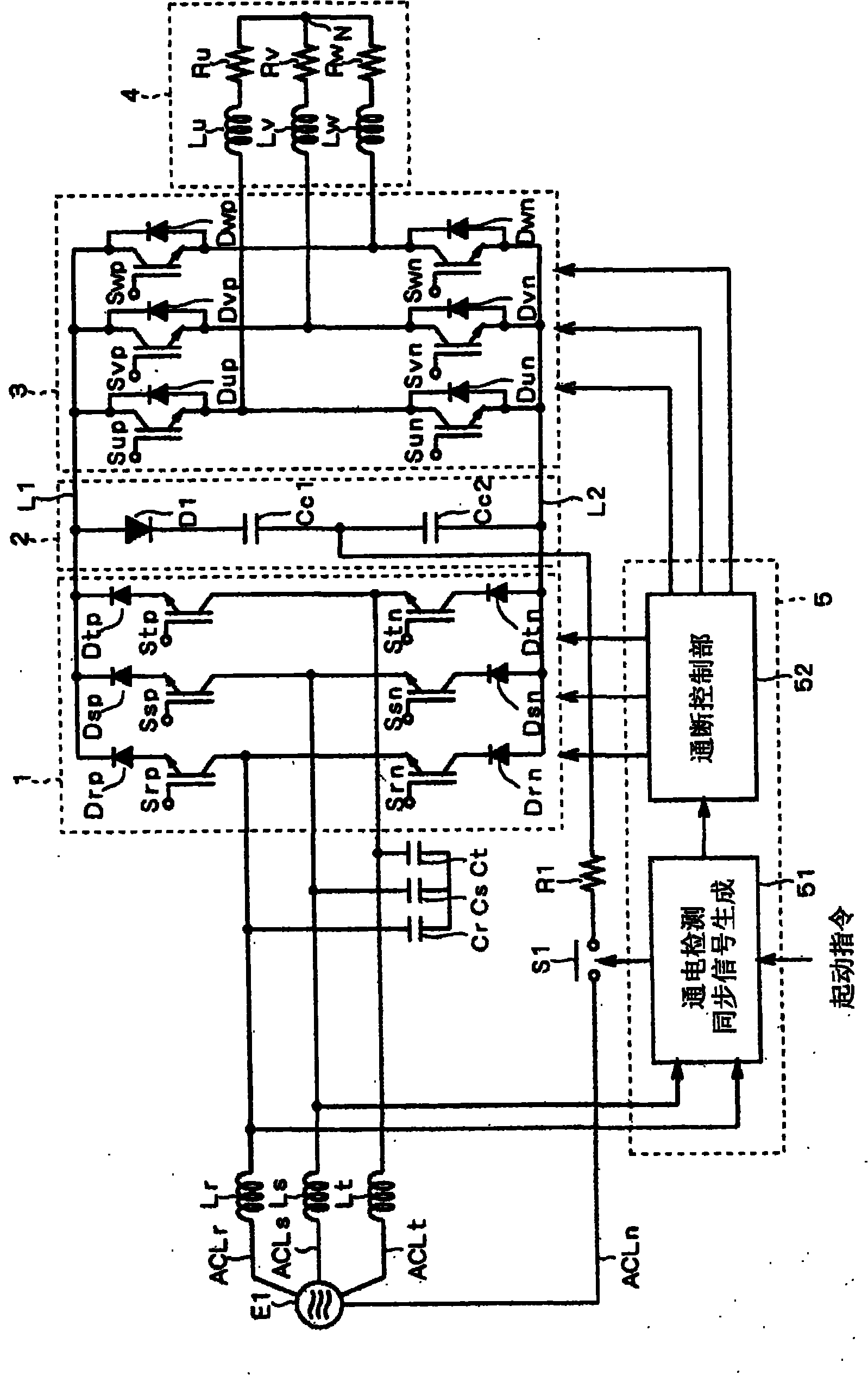
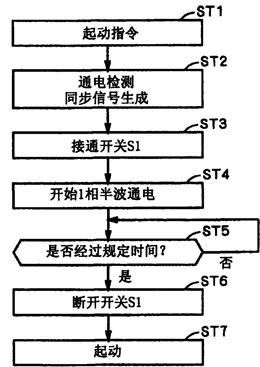
[0079] As an example of the direct AC power conversion device according to the first embodiment of the present invention, figure 1 A schematic structure of a motor drive device is shown. This motor drive device is equipped with power supply E1, input lines ACLr, ACLs, ACLt, neutral phase input line ACLn, reactors Lr, Ls, Lt, capacitors Cr, Cs, Ct, current source inverter 1, DC power line L1, L2, clamping circuit 2, voltage type inverter 3, motor 4, control part 5, resistor R1, switch S1.
[0080] The power supply E1 is a polyphase AC power supply with a neutral point (not shown), for example, a 3-phase AC power supply. The output of the power supply El is provided to input lines ACLr, ACLs and ACLt.
[0081] Each of reactors Lr, Ls, and Lt is provided on input lines ACLr, ACLs, and ACLt, respectively.
[0082] The capacitors Cr, Cs, and Ct are provided between the input lines ACLr, ACLs, and ACLt, for example, in Y-connection. Specifically, capacitors Cr and Cs are connec...
no. 2 approach
[0136] As an example of the direct power conversion device of the second embodiment, Figure 11 A schematic structure of a motor drive device is shown. The schematic structure of the motor drive device is the same as the Figure 10 Indicates the same motor drive unit. in addition, Figure 11 In FIG. 2 , circuits subsequent to the clamp circuit 2 are omitted from illustration. Alternatively, clamp circuit 2 can also be figure 1 Expressed form.
[0137] Resistors R1 to R3 are inserted into input lines ACLr, ACLs, and ACLt, respectively. The auxiliary switch Sr is connected in series with any one of the reactors Lr-Lt, Figure 9 exemplifies a configuration in which the reactor Lr is connected in series. Reactors Ls, Lt and resistors R2, R3 are connected in parallel, respectively. A combination of the auxiliary switch Sr and the reactor Lr is connected in parallel to the resistor R1.
[0138] The energization detection / synchronization signal generation unit 51 can contro...
no. 3 approach
[0153] In the direct AC power conversion device described in the first embodiment, for example, if the switch S1 remains on and switches to normal operation due to switch S1 or control failure, etc., the input line ACLr, The power line current flowing through ACLs and ACLt becomes asymmetrical, which may cause current distortion and overcurrent. First, refer to figure 1 The shown direct type AC power conversion device describes this problem in detail.
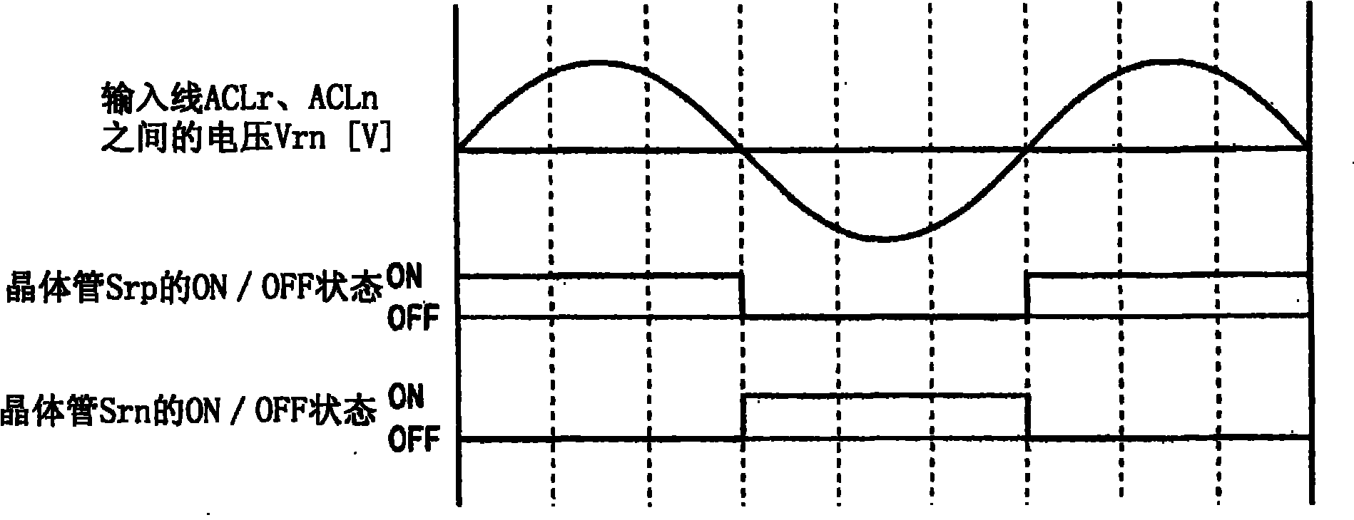
[0154] In the first embodiment, the transistors Srp, Srn, Ssp, Ssn, Stp, and Stn are used for performing normal operation. Figure 8 The dotted line shown represents the on-off action. Here, in order to simplify the description, the Figure 8 The solid line shown represents the on-off action.
[0155] Figure 15 Indicates the power supply phase voltages Vrn, Vsn and Vtn, the voltage Vc2 across the clamp capacitor Cc2, the power line currents Ir, Is, It, and the power supply neutral point line obtained when normal operatio...
PUM
 Abstract
Description
Claims
Application Information
 - R&D
- Intellectual Property
- Life Sciences
- Materials
- Tech Scout
- Unparalleled Data Quality
- Higher Quality Content
- 60% Fewer Hallucinations
Browse by: Latest US Patents, China's latest patents, Technical Efficacy Thesaurus, Application Domain, Technology Topic, Popular Technical Reports.
© 2025 PatSnap. All rights reserved.Legal|Privacy policy|Modern Slavery Act Transparency Statement|Sitemap|About US| Contact US: help@patsnap.com


