
Biomass granulation system and device

A biomass and granulation technology, applied in the direction of biofuel, waste fuel, raw material extrusion granulation, etc., can solve the problems of uncontrollable particle humidity, unstable operation of heat energy utilization equipment, scattered distribution, etc., to solve the problem of equipment investment and Reduce power consumption, facilitate high-grade utilization, and improve the effect of uniformity

Active Publication Date: 2010-08-11
邢献军
View PDF0 Cites 15 Cited by
  • Summary
  • Abstract
  • Description
  • Claims
  • Application Information

AI Technical Summary

Problems solved by technology

[0003] Although biomass fuel resources are abundant, their distribution is very scattered, and resource types and characteristics (such as shape, size, combustion characteristics, physical and chemical characteristics of ash content) vary greatly in different regions, resulting in the distribution of biomass energy resources. Collection, transportation, processing, and storage face certain difficulties; there are huge differences in the chemical composition of biomass such as moisture content, calorific value, and ash content, which brings difficulties to the thermal energy utilization of biomass
[0004] In order to overcome the difficulties in the collection, transportation, processing and storage of biomass straw, some departments have developed various biomass straw molding machines, but many related machines have some problems, such as, only for the compression molding of a single species of biomass, The energy grade of biomass fuel cannot be improved; the humidity of the formed particles cannot be controlled, resulting in unstable operation of subsequent heat energy utilization equipment; the forming machine has the disadvantage of slag dropping and low efficiency, etc.
These problems limit the rapid development of biomass fuel

Method used


Image

  • Biomass granulation system and device
  • Biomass granulation system and device
  • Biomass granulation system and device

Examples


Embodiment Construction

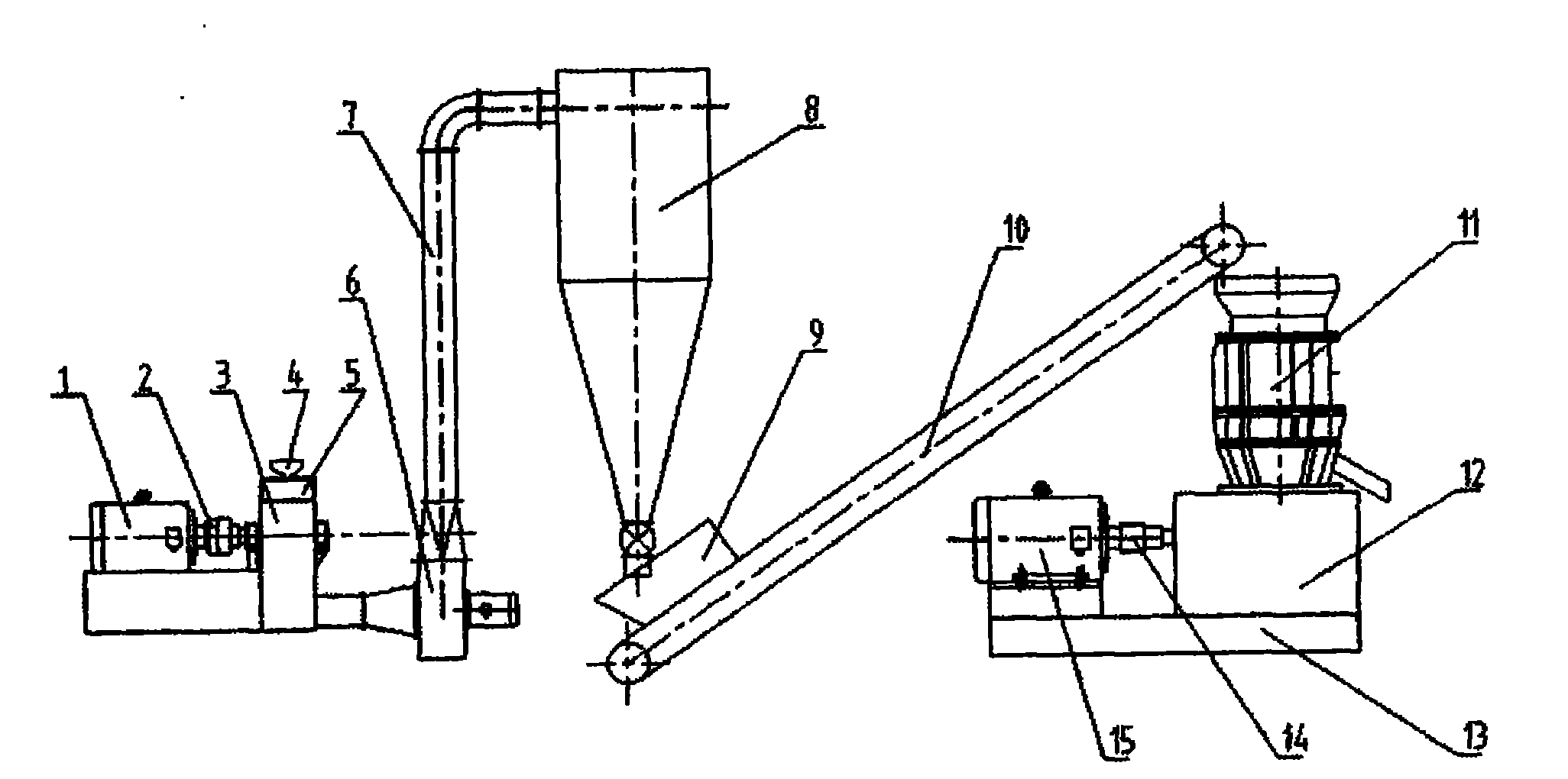
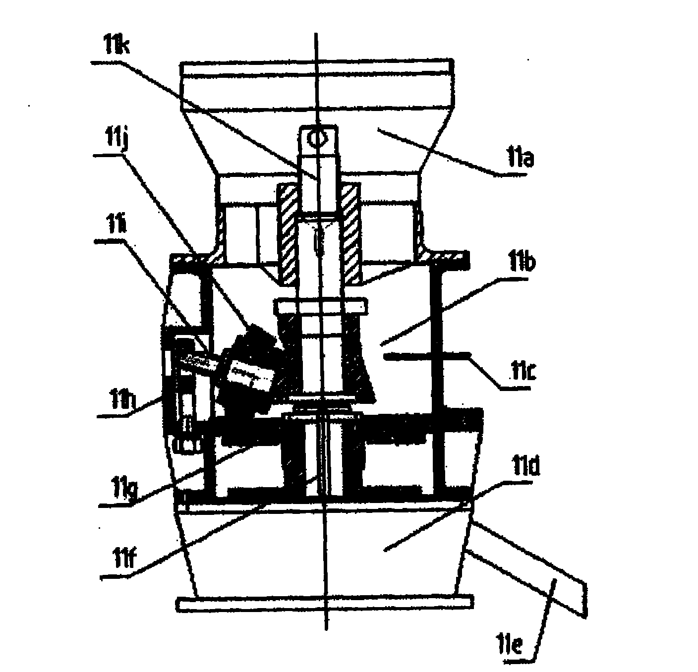
[0023] Such as figure 1 As shown, the biomass granulation system consists of a pulverizing motor 1, a coupling I 2, a pulverizer 3, an additive hopper 4, a feeding port 5, a blower 6, a feeding duct 7, a cyclone dust collector 8, and a feeding hopper 9 , Conveyor belt 10, granulator 11, gearbox 12, base 13, coupling II 14, frequency conversion motor 15 and so on.

[0024] The biomass is first sent to the pulverizer 3 for crushing, and the pulverized biomass is pumped out by the blower 6 and entered into the cyclone dust collector 8 for gas-solid separation, and the separated material is then passed through the biomass granulator 11 to make granules; the main equipment Including pulverizer 3, blower 6, cyclone dust collector 8, biomass granulator 11 and so on.

[0025] An additive hopper 4 is set at the upper end of the pulverizer 3, and pulverized coal or diatomaceous earth can be added through the additive hopper 4, which can realize mixing while pulverizing, which improves ...


PUM


Abstract

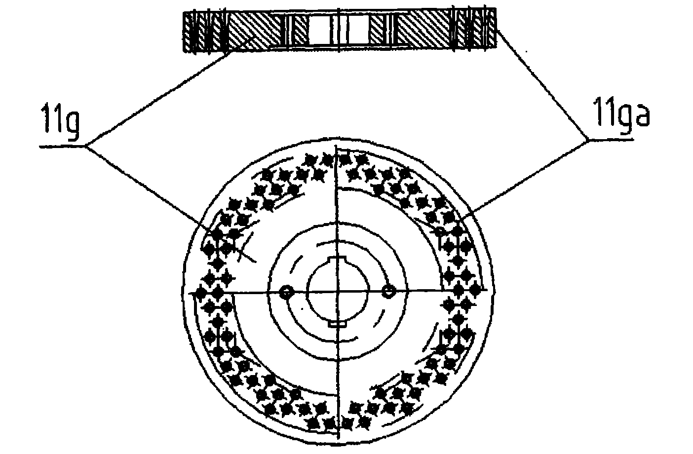
The invention discloses a biomass granulation system and a biomass granulation device. Biomass is delivered to a crusher to be crushed, the crushed biomass is pumped out through a blower and fed into a cyclone dust collector to perform gas-solid separation, and the separated material is made into granules through a biomass granulator; pulverized coal or diatomite can be added into the biomass delivered to the crusher; a temperature sensor is arranged in a molding cavity, the biomass granulator is driven by a variable frequency motor, and the rotating speed of the variable frequency motor is automatically adjusted through a monitored temperature signal; and a straight hole or a conical-straight composite through hole is formed on a flat die of the granulator. The biomass and the additive can be mixed while crushing, so the mixing uniformity of different materials is improved; the provided temperature sensor adjusts the rotating speed of the variable frequency motor and stabilizes the water content of the biomass molding granules; and the straight hole or the conical-straight composite through hole is formed on the flat die of the granulator, the molding time of the biomass granules is prolonged, the molding intensity is increased, and the slag dropping defect of the current granulator is overcome.

Description

Technical field: [0001] The invention relates to a biomass forming system and equipment, in particular to a biomass granulation system and equipment using biomass such as plant stalks, sawdust, shrubs, and weeds as main raw materials. Background technique: [0002] my country's biomass energy resources are very rich, especially as a by-product of agricultural production, crop straw has a large output and wide distribution. According to statistics, my country's annual production of biomass straw is about 800 million tons, which is equivalent to 100% of the amount of grass mowed in northern grasslands. More than 50 times, the resource possession ranks first in the world. On the one hand, the sown area of ​​crops in my country is 1.8 billion mu, and the annual production of materials is about 700 million tons. Except that part is used for papermaking and livestock feed, the rest can be used as fuel. On the other hand, my country's existing forest area is about 175 million hect...

Claims


Application Information

Patent Timeline
IPC IPC(8): B01J2/20C10L5/44
CPCY02E50/30Y02E50/10
Inventor 邢献军姜平马培勇张跃跃
Owner 邢献军
Learn More