Cathode device for carrying out linear reactive sputtering film coating by utilizing electric-field confinded plasmas

A plasma and sputtering coating technology, which is applied in the direction of sputtering coating, ion implantation coating, vacuum evaporation coating, etc., can solve the problems of insignificant gas disturbance effect, energy loss of argon gas, and reduction of plasma density, etc. Achieve uniform distribution of working gas, make up for the decrease in deposition rate, and prevent the effect of entering the target cavity

Active Publication Date: 2010-08-11
苏州力合光电薄膜科技有限公司
View PDF7 Cites 11 Cited by
  • Summary
  • Abstract
  • Description
  • Claims
  • Application Information

AI Technical Summary

Problems solved by technology

In order to prevent this phenomenon, Alan Delahoy et al. invented the gas disturbance method to prevent oxygen from contacting the target (US Patent 7235160), but when the target is relatively wide and the target distance is relatively small, the gas disturbance effect becomes insignificant, especially At the outlet of the argon gas, this is because the argon gas with a certain initial velocity continuously collides and rubs against the surface of the parallel target, causing the argon gas to lose energy and slow down. The speed of argon at the surface

Method used


Image

  • Cathode device for carrying out linear reactive sputtering film coating by utilizing electric-field confinded plasmas
  • Cathode device for carrying out linear reactive sputtering film coating by utilizing electric-field confinded plasmas
  • Cathode device for carrying out linear reactive sputtering film coating by utilizing electric-field confinded plasmas

Examples


Embodiment Construction

[0031] The present invention will be further described below in conjunction with accompanying drawing and embodiment:

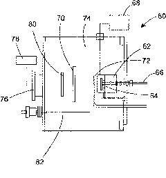
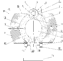
[0032] See attached image 3 As shown, an electric field confined plasma linear reactive sputtering coating cathode device includes: a pair of target frames 7, a first target material 8 that is oppositely arranged on the target frame 7 and extends longitudinally. And the second target material 82, working gas source 1, reaction gas source, the two side surfaces of a pair of described target frame 7 are all provided with insulating layer 15, described first target material 81 and second target material The two opposite side walls of the material 82 are respectively inwardly recessed to form a sputtering surface 21, and a target cavity 11 is formed between a pair of sputtering surfaces 21; 14-phase electrical connection, the working gas source 1 and the reaction gas source are respectively located on the inlet 17 side and the outlet 18 side of the target chamb...


PUM


Abstract

The invention relates to a cathode device for carrying out linear reactive sputtering film coating by utilizing electric-field confinded plasmas, comprising a target stand, a working gas source, a reaction gas source and a first target material and a second target material which are oppositely arranged on the target stand and respectively extend along the longitudinal direction, wherein the two opposite side wall surfaces of the first target material and the second target material respectively concave inwards to form sputtering surfaces, and a target cavity is formed between the two sputtering surfaces; the working gas source and the reaction gas source are respectively arranged at the inlet side and the outlet side of the target cavity; and on the cross section of the cathode device, the minimum distance between the two sputtering surfaces is at the outlet position of the target cavity. In the invention, the distribution of electric fields is changed by changing the shape of the target material, and the direction of the strength of the electric field in the target cavity is along the direction being vertical to the sputtering surfaces, and therefore, the plasmas are intensively confined in the central areas of the pair of target materials, which increases the density of the target materials and further improves the sputtering rate. Meanwhile, the invention also can effectively prevent reaction gas from entering the target cavity, and thereby, target poisoning is avoided.

Description

technical field [0001] The invention relates to a sputter coating cathode device. Background technique [0002] Most of the sputtering coating methods commonly used in the prior art are magnetron sputtering coating technology, that is, using a magnetic field to confine the plasma, and under low pressure, the target atoms are sputtered out by high-energy ions and deposited on the substrate to achieve the coating. the goal of. The biggest disadvantage of this method is that during reactive sputtering coating, the reactive gas source will interact with the surface of the target to oxidize it (target poisoning phenomenon). This can greatly affect the deposition rate and film properties. In recent years, a new sputtering coating method has been proposed. This method uses high-speed argon to pass between two parallel targets, and the working gas source is outside the target chamber, which is repelled by argon. , It is difficult for the working gas source to touch the target sur...

Claims


Application Information

Patent Timeline
IPC IPC(8): C23C14/34
Inventor 郭射宇
Owner 苏州力合光电薄膜科技有限公司
Why Eureka
Try Eureka