Grid type transverse air-intake turbulent flow type electric dust remover

An electrostatic precipitator, horizontal technology, applied in the field of grid-type horizontal air inlet turbulent-flow electrostatic precipitator, can solve the problems of poor rapping effect, large area occupied by the electrostatic precipitator, poor overload capacity, etc., and achieves The effect of prolonging the movement distance and running time, stabilizing the dust content of the exhaust gas, and high absorption capacity

Active Publication Date: 2010-08-18
LIAOCHENG LUXI CHEM ENG DESIGN
View PDF4 Cites 15 Cited by
  • Summary
  • Abstract
  • Description
  • Claims
  • Application Information

AI Technical Summary

Problems solved by technology

[0005] 1. The flow state and direction of exhaust gas limit its adsorption capacity for fine dust;
[0006] 2. To meet the increasingly stringent national environmental protection requirements, we can only increase the number of electric fields (more than 5 electric fields) or increase the cross-sectional area of ​​exhaust gas flow to reduce the flow cross-sectional velocity of exhaust gas, resulting in a large consumption of steel for conventional (current) electrostatic precipitators , occupying a larger space;
[0007] 3. For the treatment of tail gas containing high specific resistance dust, it is necessary to carry out tempering and take measures such as increasing the number of electric fields to meet the exhaust emission requirements. The dust removal system is complicated, the operation workload is heavy, and even: ① Accidents caused by "excessive conditioning and tempering", resulting in shutdown of the electrostatic precipitator or even system shutdown;
[0008] 4. The rapping hammer of the cathode system of the conventional electrostatic precipitator is hammered on the frame composed of several square steels connected to the cathode line. The rapping force is scattered and the rapping effect is not good;
[0009] 5. The daily maintenance and maintenance workload is heavy, and the operating cost is high;
[0010] 6. Unstable operation and poor overload capacity

Method used


Image

  • Grid type transverse air-intake turbulent flow type electric dust remover
  • Grid type transverse air-intake turbulent flow type electric dust remover
  • Grid type transverse air-intake turbulent flow type electric dust remover

Examples


Embodiment Construction

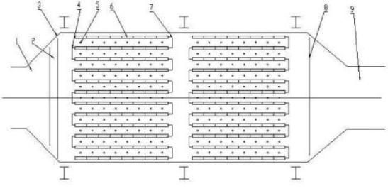
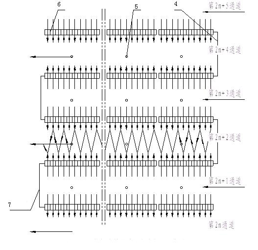
[0025] The grid-type transverse air inlet turbulent flow electrostatic precipitator includes a dust removal device and a vibrator. The dust removal device uses the horizontal turbulent air inlet grille 6 as the anode plate, and the transverse turbulent air inlet grille 6 has multiple rows and is parallel to the The air flow is set, and the cathode line 5 and the gap as the flue gas passage are arranged between two adjacent pieces of each row of transverse turbulent flow inlet grilles 6, and the front end of the flue gas passage formed by each row of transverse turbulent flow inlet grilles 6 The front sealing plate 4 is arranged at intervals to form a high-voltage electric field outlet channel, and the rear sealing plate 7 is arranged at intervals to form a high-voltage electric field inlet channel, and the high-voltage electric field outlet channel is adjacent to the high-voltage electric field inlet channel.

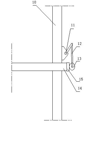
[0026] The cathode wire 5 is fixed on the cathode frame 14. The cat...


PUM


Abstract

The invention relates to a grid type transverse air-intake turbulent flow type electric dust remover comprising a dust removing device and a vibrator, wherein the dust removing device uses mutliple rows of transverse turbulent flow air-intake grid plates as anode plates, the transverse turbulent flow air-intake grid plates are parallel to an air flow, a cathode wire and a gap used as a flue gas channel are arranged between the adjacent transverse turbulent flow air-intake grid plates in each row, the front ends of the flue gas channels formed by each row of transverse turbulent flow air-intake grid plates are provided with front seal plates at intervals to form a high-voltage electric field outlet channel, the back ends are provided with back seal plates at intervals to form a high-voltage electric field inlet channel, and the high-voltage electric field outlet channel is adjacent to the high-voltage electric field inlet channel. The invention adopts grid type transverse air intake to replace the longitudinal air intake of the conventional dust remover so that tail gas in the electric dust remover is changed into a novel turbulent flow state from the conventional basic layer flow state, the moving route and the running time of charged particles in the dust remover are prolonged so that the opportunity of capturing the charged particles close to or even directly contacting an easy-absorption pole is greatly increased, and meanwhile, a vibration system has a good effect to ensure that the polar plates of the dust remover are clean.

Description

technical field [0001] The invention relates to an electric precipitator, in particular to a grid-type transverse air-inlet turbulent-flow electric precipitator. Background technique [0002] At present, the situation of the new and in-use electric dust collectors for furnace tail gas is that after the tail gas enters the dust collector and passes through the air flow uniform distribution device, it basically enters the high-voltage electric field area of ​​the electric dust collector in a laminar flow state along the longitudinal direction of the dust collector, and the dust particles in the tail gas After being charged in the high-voltage electric field, the negatively charged dust particles are gradually driven to the anode plate, and are captured by the anode plate after reaching the surface of the anode plate, and the positively charged dust particles are driven to the cathode line, and are captured by the cathode line after reaching the surface of the cathode line. Whe...

Claims


Application Information

Patent Timeline
Patent Type & Authority Applications(China)
IPC IPC(8): B03C3/08B03C3/47B03C3/86B03C3/76
Inventor 张雷齐树杰
Owner LIAOCHENG LUXI CHEM ENG DESIGN
Why Eureka
Try Eureka