Bottom cathode diversion type rare earth electrolysis cell

A bottom cathode and electrolytic cell technology, applied in the field of metallurgy, can solve problems such as the great influence of molten metal, restriction amplification, heat loss, etc., and achieve the effects of increasing metal yield, reducing metal secondary oxidation, and reducing residence time

Inactive Publication Date: 2010-08-18
INNER MONGOLIA UNIV OF SCI & TECH
View PDF8 Cites 18 Cited by
  • Summary
  • Abstract
  • Description
  • Claims
  • Application Information

AI Technical Summary

Problems solved by technology

[0003] At present, rare earth metal electrolysis using oxides as raw materials and fluoride as molten salt system is an important method for producing rare earth metals. Due to the strong corrosiveness of high temperature fluoride molten salts, the electrolysis of oxides in fluoride molten salt systems The research has brought great difficulties. There are two main development directions in the process of large-scale electrolyzer cell type. One is still using the open-type upwardly inserted cathode and anode mode designed in the 1980s in terms of electrode configuration, such as Chinese patents CN2372329Y, CN2632099Y, CN2464744Y, CN02240881.9 and CN200820138112.3, the current efficiency is about 80% at present, and the current intensity is about 20KA. During the enlargement process of this structure, due to the problem of its complex wiring structure, the upper part has a large opening, and the tank body has no insulation measures , the heat loss is serious, and

Method used


Image

  • Bottom cathode diversion type rare earth electrolysis cell
  • Bottom cathode diversion type rare earth electrolysis cell
  • Bottom cathode diversion type rare earth electrolysis cell

Examples


Embodiment Construction

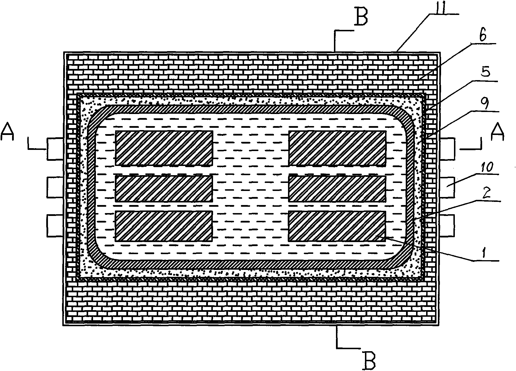
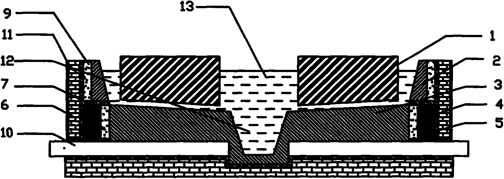
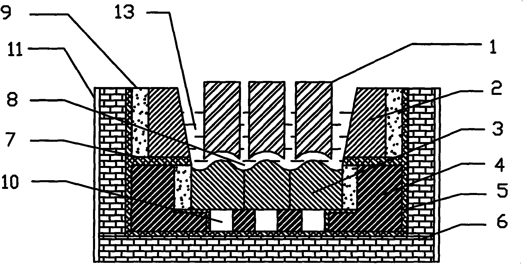
[0016] As attached figure 1 , Attached figure 2 , Attached image 3 As shown, the present invention includes: anode 1, graphite crucible 2, cathode, refractory layer 4, insulating layer 5, heat preservation layer 6, high temperature insulating layer 7, flow channel 8, carbon powder layer 9, cathode conductive row 10, protective layer 11. Metal collector 12, electrolyte 13. The body of the rare earth electrolytic cell is a masonry rectangular graphite crucible 2 or a trapezoidal graphite crucible 2 with a large upper and a small opening. The trapezoidal graphite crucible 2 with a larger opening at the upper end and a smaller opening at the lower end is used to facilitate the discharge of gas. The carbon powder layer 9 is filled between the graphite crucible 2 and the insulating layer 5, which can ensure that the electrolysis is carried out without leakage, improve the utilization rate of electric energy, and reduce energy consumption. The refractory layer 4, the insulation lay...


PUM


Abstract

The invention relates to an electrolysis cell in the metallurgy field, in particular to a bottom cathode diversion type rare earth electrolysis cell which is suitable for improvement and development of a rare earth electrolysis cell. In the invention, cathodes are arranged just below anodes, the bottom of each anode is an arc concave surface, the top part of each cathode is an arc convex surface, the arc concave surface of each anode is arranged corresponding to the arc convex surface of each cathode, the cathodes are arranged in parallel, a diversion cell is formed at the connecting part of the cathodes, a high temperature insulating layer is arranged between the cathodes and a graphite crucible, and a cathode conductive bar is arranged below the cathodes. In the invention, a novel cathode and anode structure is designed, the requirement of high current density of the cathode and low current density of the anode in the electrolysis process because rare metals are all lively is met, the residence time of electrolysis metal drops in an electrolysis region is reduced by adopting a diversion type cathode structure, the secondary oxidation of the metals can be effectively reduced, the metal yield is improved, mature wiring mode and technology of the traditional electrolysis cell are effectively utilized by adopting the bottom cathode arrangement mode, and the generalization and macro-scale of the cell type are facilitated.

Description

Technical field [0001] The invention relates to an electrolytic cell in the field of metallurgy, in particular to a bottom cathode guide type rare earth electrolytic cell, which is suitable for the transformation and development of the rare earth electrolytic cell. Background technique [0002] Rare earth metals are one of the main raw materials of rare earth functional materials. As a strategic resource of our country, their demand is increasing. With the expansion of production scale, the correction of trough structure has attracted more and more attention in the industry. [0003] At present, the electrolysis of rare earth metals using oxides as raw materials and fluoride as the molten salt system is an important method for preparing rare earth metals. Because high-temperature fluoride molten salts are extremely corrosive, the electrolysis of oxides in the fluoride molten salt system is very important. The research has brought great difficulties. There are two main development ...

Claims


Application Information

Patent Timeline
IPC IPC(8): C25C3/34
Inventor 伍永福刘中兴李保卫武文斐赵增武冯化超
Owner INNER MONGOLIA UNIV OF SCI & TECH
Why Eureka
Try Eureka