Large-power LED lamp heat radiator with fins having functions of heat pipes

An LED lamp, high-power technology, used in lighting and heating equipment, cooling/heating devices for lighting devices, lighting devices, etc. It has the advantages of convenient processing, production and installation, easy operation, simple and reasonable structure

Inactive Publication Date: 2010-08-18
NORTHWEST INSTITUTE FOR NON-FERROUS METAL RESEARCH
View PDF8 Cites 23 Cited by
  • Summary
  • Abstract
  • Description
  • Claims
  • Application Information

AI Technical Summary

Problems solved by technology

For high-power LEDs with a power of several watts to hundreds of watts used in lighting, if no heat dissipation measures are taken, the junction temperature of the LED chip will rise rapidly, resulting in a sharp decrease in the light output rate and life of the LED, especially when the junction temperature rises above At the maximum allowable temperature (generally 125°C), the LED will fail due to overheating
Currently, there are three main technical solutions for high-power LED heat dissipation: one is to use heat pipes and solid heat dissipation fins to dissipate heat; The working principle is to export the heat generated by the LED chip through the heat pipe, and then transfer the exported heat to the solid-core fin through the heat pipe, and then dissipate the heat through the solid-core fin. Even if the solid-core fin is made of copper, its thermal conductivity It is only 398W / mK, which is 2 orders of magnitude lower than the thermal conductivity of the heat pipe. Since the thermal conductivity of the solid-core fin is much lower than that of the heat pipe, the temperature difference on the solid-core fin is relatively large, and it is difficult to reduce the thermal conductivity of the LED chip. It is also difficult to quickly dissipate the heat, so the above two heat sinks are difficult to meet the heat dissipation requirements of high-power LEDs in the state of natural convection; the third is to increase the forced convection cooling device of the fan to dissipate heat, and the heat sink with the fan not only increases Reduced power consumption and reduced system reliability, unable to achieve energy-saving, safety, and long-life goals of LEDs
To sum up, the currently used LED heat dissipation technology solutions have various defects and deficiencies such as poor heat dissipation effect, high energy consumption, and poor reliability to varying degrees, which still limit the wide application of high-power LED lights to a large extent. application

Method used


Image

  • Large-power LED lamp heat radiator with fins having functions of heat pipes
  • Large-power LED lamp heat radiator with fins having functions of heat pipes
  • Large-power LED lamp heat radiator with fins having functions of heat pipes

Examples


Embodiment 1

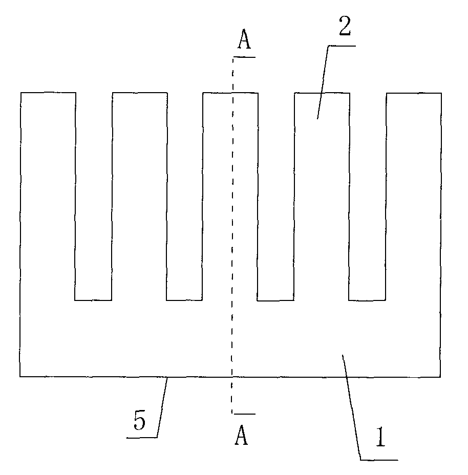
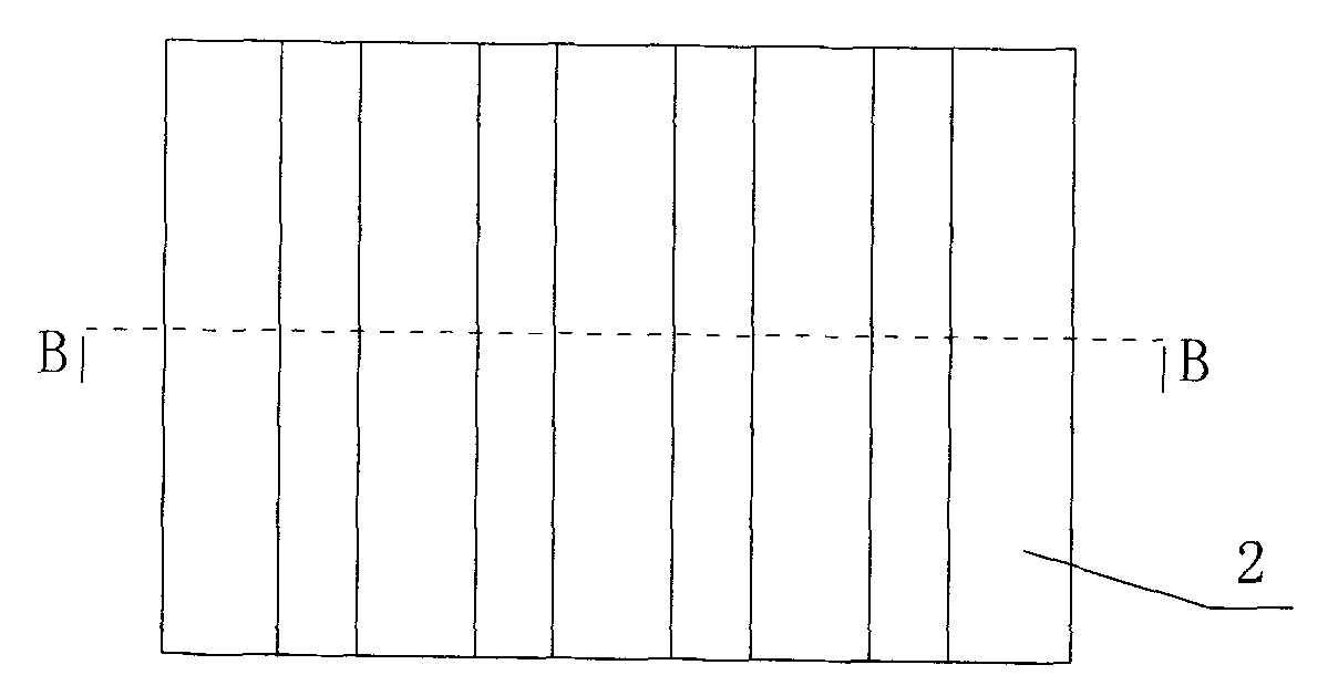
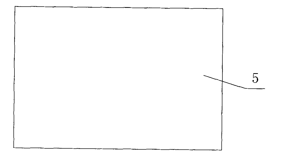
[0032] Such as figure 1 , figure 2 , image 3 , Figure 4 and Figure 5 As shown, the present invention includes a metal heat dissipation body 1 and metal heat dissipation fins 2 arranged on the metal heat dissipation body 1, the number of the metal heat dissipation fins 2 is not less than one piece, and the metal heat dissipation body 1 is provided with There is a fixed installation surface 5 for the fixed installation of the high-power LED light source. Both the metal heat dissipation body 1 and the metal heat dissipation fins 2 are hollow structures. The first hollow cavity inside the metal heat dissipation body 1 communicates with the second hollow cavity inside the metal heat dissipation fin 2 to form a closed inner hollow cavity 3 that communicates with each other.

[0033] A heat pipe liquid-absorbing core 4 is arranged on the inner wall of the closed inner cavity body 3 and a working liquid is housed inside. The heat dissipation body 1 and the metal heat dissipat...

Embodiment 2

[0038] Such as Figure 6 , Figure 7 , Figure 8 , Figure 9 and Figure 10 As shown, in this embodiment, the difference from Embodiment 1 is that: the metal heat dissipation body 1 is a cylindrical structure, the number of the metal heat dissipation fins 2 is multiple, and the plurality of metal heat dissipation fins 2. Taking the central axis of the metal heat dissipation body 1 as the center line, it is radially and evenly arranged on the surrounding outer edge of the metal heat dissipation body 1. The fixed installation surface 5 is arranged on the lower end surface of the metal heat dissipation body 1 . Specifically: the number of the metal heat dissipation fins 2 is 12, and the 12 metal heat dissipation fins 2 are all in the shape of a cuboid and have the same structure and size. When actually laid out, the 12 metal heat dissipation fins 2 They are arranged radially and evenly around the outer sides of the cylindrical metal heat dissipation body 1, and the assembled...


PUM


Abstract

The invention discloses a large-power LED lamp heat radiator with fins having functions of heat pipes, which comprises a metallic heat radiating body and at least one metallic heat radiating fin, wherein the metallic heat radiating body and the metallic heat radiating fin are both in a hollow structure; a first hollow cavity in the interior of the metallic heat radiating body is communicated with a second hollow cavity in the interior of the metallic heat radiating fin to form an intercommunicated closed type inner cavity body; a heat pipe fluid absorbing core is arranged on the inner wall of the closed type inner cavity body, and operating fluid is filled in the heat pipe fluid absorbing core; the heat radiating body and the metallic heat radiating fin correspondingly form an integrated heat pipe for heat exchange; the inner wall of the heat radiating body and the inner wall of the metallic heat radiating fin form a pipe shell of the integrated heat pipe; and the heat radiating body and the metallic heat radiating fin have functions of heat pipes. The invention has the advantages of simple and reasonable structure, small volume, convenient processing, manufacture, installation and arrangement, large heat radiating area, high heat conduction coefficient and good heat radiating performance, and can effectively solve the heat radiating problem of large-power LED lamps.

Description

technical field [0001] The invention relates to a high-power LED lamp radiator, in particular to a high-power LED lamp radiator whose fins have the function of heat pipes. Background technique [0002] Light-emitting diode (LED) is a new energy-saving and environmentally friendly green light source. Compared with traditional lighting such as incandescent lamps, fluorescent lamps or high-pressure sodium lamps, LEDs can save 50-70% of electric energy and 70% of cable costs. Extensive research, promotion and application of LEDs have been carried out internationally, among which LEDs with a power of less than 1W have been widely used in the fields of indication, display and backlight. LED is a photoelectric device with a theoretical lifespan of up to 100,000 hours. During the working process, about 15% of the electrical energy is converted into light energy, and almost all the rest of the electrical energy is converted into heat energy. For high-power LEDs with a power of sever...

Claims


Application Information

Patent Timeline
Patent Type & Authority Applications(China)
IPC IPC(8): F21V29/00F21Y101/02F21V29/503F21V29/51F21V29/74F21V29/89
Inventor 华云峰李争显杜明焕杜继红王彦峰
Owner NORTHWEST INSTITUTE FOR NON-FERROUS METAL RESEARCH
Why Eureka
Try Eureka