
Climate environment simulation test method

A technology for simulating test and climate environment, applied in the test field, can solve the problems of no large-scale simulation, high cost, high energy consumption, etc., and achieve the effect of reducing test cost and low cost

Active Publication Date: 2010-08-18
CHINA ELECTRIC POWER RES INST +1
View PDF4 Cites 30 Cited by
  • Summary
  • Abstract
  • Description
  • Claims
  • Application Information

AI Technical Summary

Problems solved by technology

However, at present, the environmental simulation test equipment at home and abroad is mainly designed for a single meteorological condition, and there is no large-scale high-altitude simulation laboratory at home and abroad, and the impact of high altitude on flashover characteristics is relatively small. and ice flash effects can only be done in a small climate chamber for some short series of experiments or mechanistic studies
Although there are some comprehensive environmental simulation test devices at home and abroad, these devices are not comprehensive enough to simulate complex meteorological environments
For example, a multi-functional artificial climate chamber system disclosed in the prior art can artificially simulate meteorological environments such as fogging and icing, but it lacks an independent ice-melting system and a simulated high-altitude system, and its ice-melting process only depends on the laboratory The temperature control system is used to achieve ice melting, which not only consumes a lot of energy and costs, but also makes it difficult to control the speed of ice melting
In addition, the artificial climate tanks currently developed in China for electrical tests are small in size, which cannot meet the requirements for research on the flashover characteristics of EHV, UHV insulators and large insulator strings.

Method used


Image

  • Climate environment simulation test method
  • Climate environment simulation test method
  • Climate environment simulation test method

Examples


Embodiment Construction

[0016] The method of the present invention will be described in detail below with reference to the accompanying drawings and embodiments.

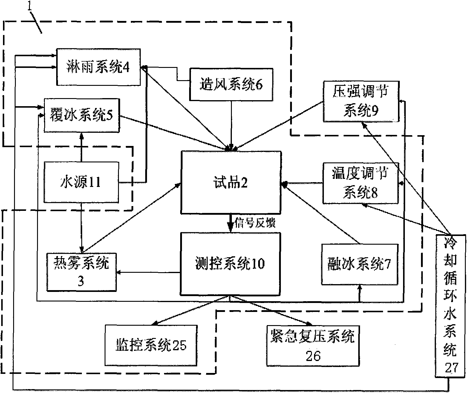
[0017] like figure 1 As shown, in order to realize the method of the present invention, it is first necessary to set up an environmental simulation cabin 1, and in the environmental simulation cabin 1, a test product 2 connected with UHV electricity, a thermal fog system 3, a rain system 4, and an ice coating system 5 are set up. , wind generation system 6 , ice melting system 7 and temperature adjustment system 8 , a pressure adjustment system 9 , a measurement and control system 10 and a water source 11 are arranged outside the environmental simulation cabin 1 .

[0018] The environmental simulation cabin 1 is a sealed environment simulation test site, and the environmental simulation cabin 1 needs to meet the following requirements:

[0019] Temperature rise rate ΔT / t<1K / h, where: T is absolute temperature, t is time;

[0020] The pre...


PUM


Abstract

The invention relates to a climate environment simulation test method which comprises the following operation that: an environment simulation cabin is arranged; a sample fed with ultrahigh-voltage power is arranged in the environment simulation cabin; a thermal fog system, a rain spray system, an ice covering system, a wind creating system and an ice melting system are arranged around the sample, and a temperature control system, a pressure regulation system, a test control system and a water source are arranged outside the environment simulation cabin; when the thermal fog environment is simulated, the thermal fog system is controlled to input the rate of steam into the environment simulation cabin; when the rain spraying environment is simulated, the angle that rain drops collide with the surface of the sample is 45 degrees; when the ice covering environment is simulated, the temperature in the environment simulation cabin is controlled, so that water drops are attached on the surface of the sample; when wind environment is simulated, the wind speed of the wind creating system is controlled; and the ice melting environment is simulated, the temperature rise rate near the sample is controlled. The climate environment simulation test method is easy to simulate various climate environments, can be applied in the test research and the product performance test of electric power, traffic, aviation and other fields, and the like.

Description

technical field [0001] The invention relates to a test method, in particular to a climate environment simulation test method. Background technique [0002] In recent years, with the increasing domestic power demand, UHV power transmission has become an important means to improve the transmission capacity of my country's power grid. Since the insulator strings in UHV lines are exposed to the outdoors, a contamination layer composed of soluble salts and insoluble ash will be deposited on the surface, and there is high voltage at both ends of the insulator strings. The performance is degraded, especially in foggy, rainy or freezing days, there may also be a large leakage current on the surface of the insulator string, which is often referred to as flickering. More seriously, the flickering phenomenon on the surface of the insulator string may cause phase-to-phase short circuit or phase-to-ground short circuit, resulting in major safety accidents such as large-scale power outag...

Claims


Application Information

Patent Timeline
IPC IPC(8): G01R31/12
Inventor 宿志一范建斌周军王浚黄勇于昕哲
Owner CHINA ELECTRIC POWER RES INST
Learn More