Lithium ion power battery cap and welding method thereof

A power battery and welding method technology, which is applied to battery pack parts, circuits, electrical components, etc., can solve the problems of lower battery performance level, increased battery resistance, and weak contact, etc., to achieve small contact resistance and low production efficiency , a wide range of effects

Inactive Publication Date: 2010-08-18
TIANJIN CHUNYU ELECTRONICS MACHINERY
View PDF3 Cites 5 Cited by
  • Summary
  • Abstract
  • Description
  • Claims
  • Application Information

AI Technical Summary

Problems solved by technology

The contact between the top cover of the existing cap and the explosion-proof diaphragm is not firm, or the welding method of adding a transition layer in the middle is used for processing, which has technical problems such as complex process, high production cost, and low production efficiency. Moreover, it affects the resistance increase of the battery. Large, causing resistance drift, directly reducing the performance level of the battery, posing safety hazards, and even causing major accidents, etc.

Method used


Image

  • Lithium ion power battery cap and welding method thereof
  • Lithium ion power battery cap and welding method thereof
  • Lithium ion power battery cap and welding method thereof

Examples


Embodiment 1

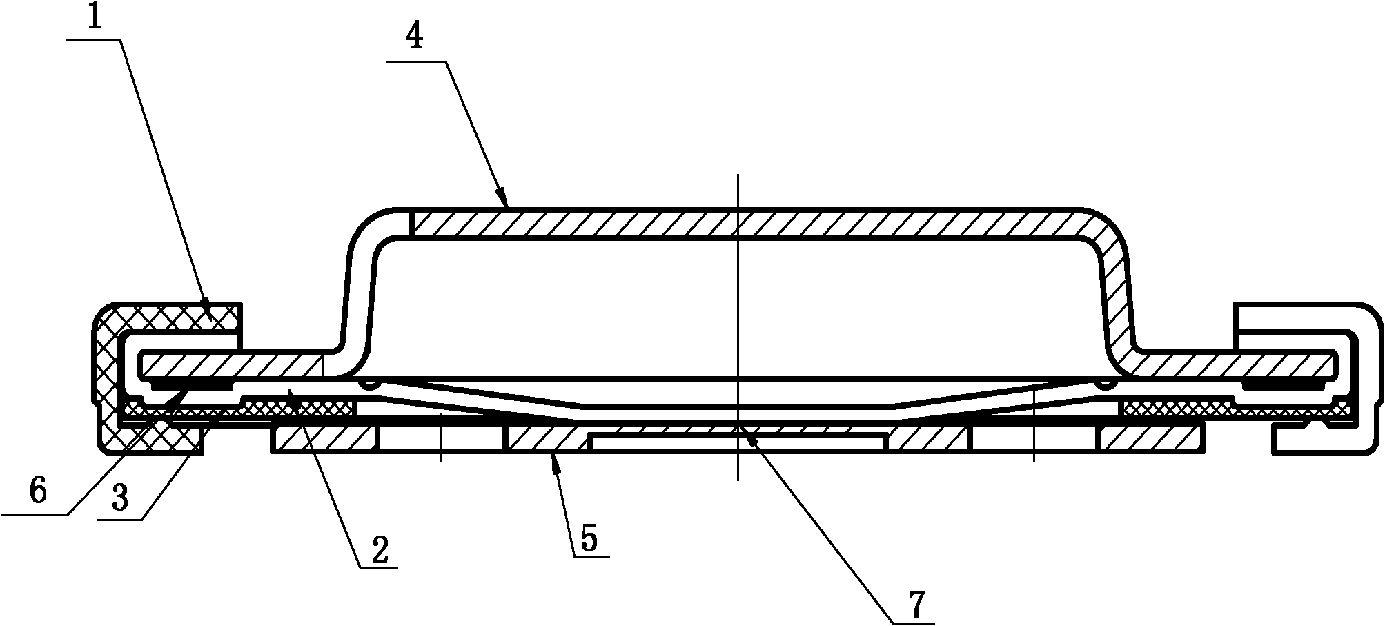
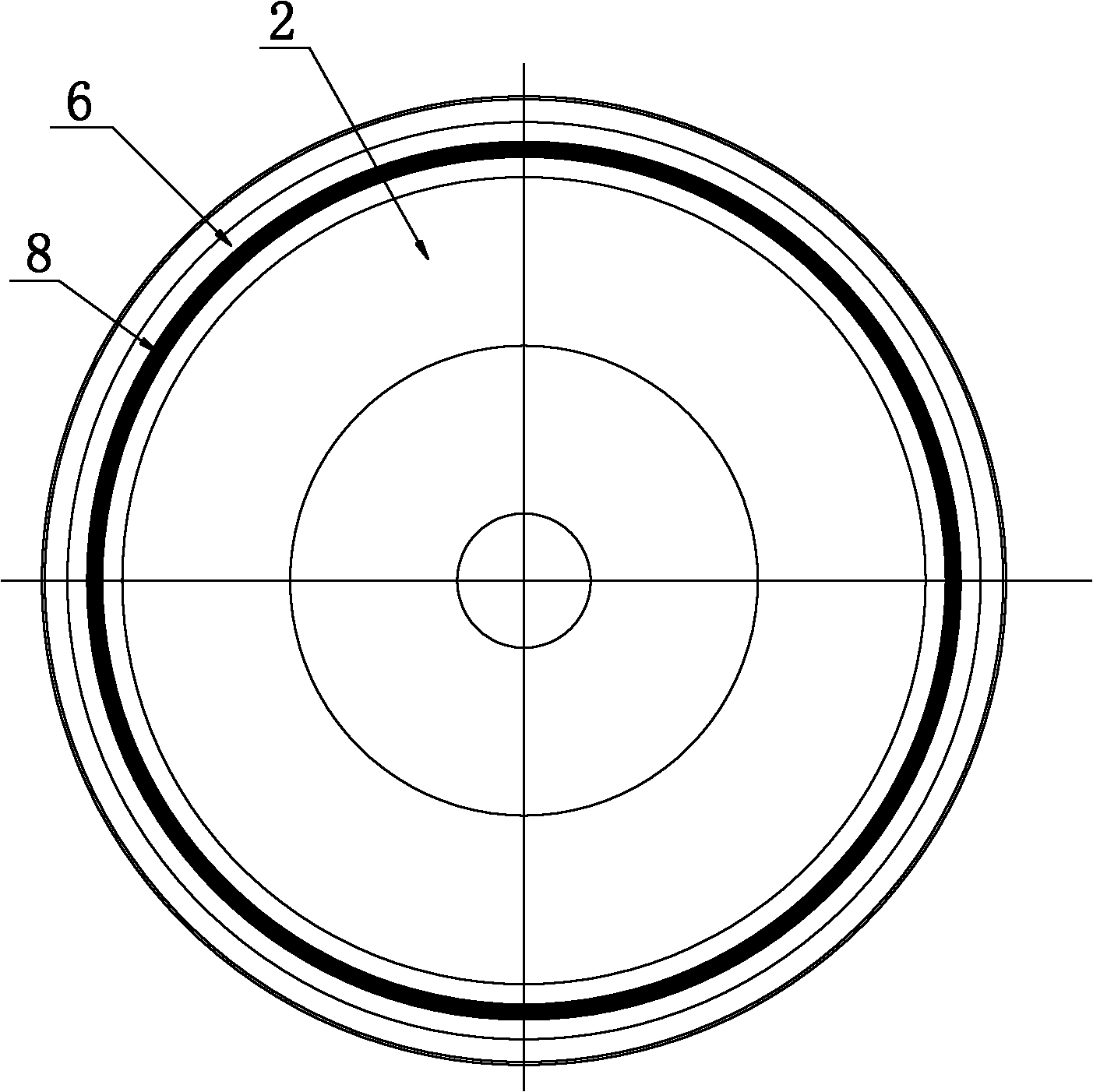
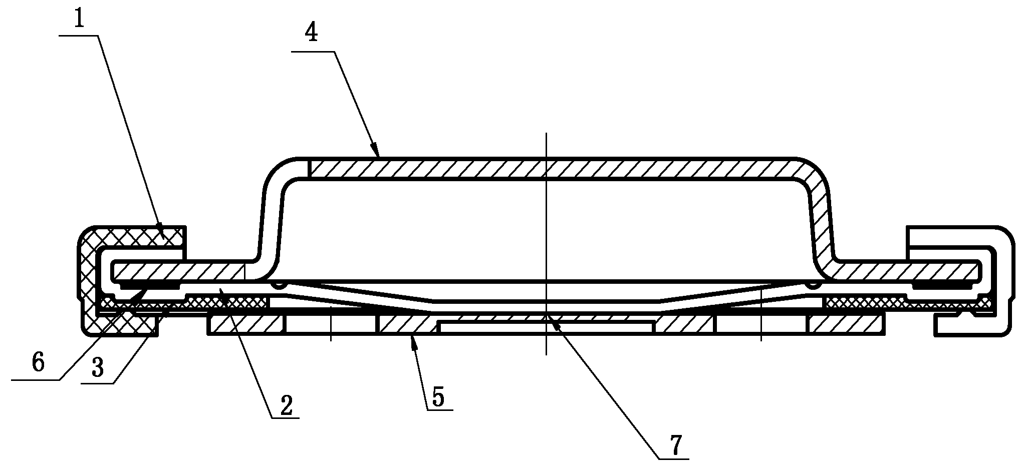
[0017] Embodiment 1 A lithium-ion power battery cap, including a top cover 4, an explosion-proof diaphragm 2, a gasket 3 and a pole plate 5, the top cover 4 is combined with the explosion-proof diaphragm 2, the gasket 3 and the pole plate 5 in sequence, and there are sealing ring 1. The explosion-proof diaphragm 2 has an overall circular welding groove 6, the overall circular welding groove 6 has a depth of 0.05mm and a width of 1.5mm. There are brazing tin wires 8 for the top cover and the explosion-proof diaphragm in the groove, and the top cover and the explosion-proof diaphragm are connected by brazing. The explosion-proof diaphragm and the pole plate have 6 uniform welding spots at the laser welding place 7 .

Embodiment 2

[0018] Embodiment 2 A lithium-ion power battery cap welding method, the top cap, explosion-proof diaphragm, gasket and pole plate are assembled together in sequence, and a sealing ring is added. When processing the top cover and the explosion-proof diaphragm, punch out a circular groove on the top cover and the explosion-proof diaphragm, place brazing tin wire in the groove of the top cover or the explosion-proof diaphragm, and solder the top cover It is welded with the explosion-proof diaphragm to form an integral structure.

[0019] The lithium-ion power battery cap and its welding method have the advantages of novel technology, convenient processing, simple structure, firm contact, small contact resistance, no resistance drift, high safety level, long battery life, wide application range and the like.


PUM

PropertyMeasurementUnit
depthaaaaaaaaaa
widthaaaaaaaaaa
depthaaaaaaaaaa

Abstract

The invention relates to a lithium ion power battery cap and a welding method thereof, which belong to the technical field of lithium ion batteries. The lithium ion power battery cap comprises a top cover, an anti-explosion membrane, a gasket and a polar plate, wherein the top cover, the anti-explosion membrane, the gasket and the polar plate are sequentially combined. The invention is characterized in that a groove is formed on the top cover or on the anti-explosion membrane, brazing materials of the top cover and the anti-explosion membrane are arranged in the groove, and the top cover and the anti-explosion membrane are in a connection structure in a brazing mode. The welding method of the lithium ion power battery cap has the following steps: sequentially assembling the top cover, the anti-explosion membrane, the gasket and the polar plate; and additionally adding a sealing ring. The invention is characterized in that when the top cover and the anti-explosion membrane are processed, firstly, the groove is manufactured on the top cover and the anti-explosion membrane, the brazing materials are placed in the groove of the top cover or the anti-explosion membrane, and the top cover and the anti-explosion membrane are welded into an integral structure through brazing. The invention has the advantages of novel technology, convenient processing, firm contact, small contact resistance, no resistance drift, high safety grade, long service life of the battery, wide application range and the like.

Description

technical field [0001] The invention belongs to the technical field of lithium-ion batteries, in particular to a lithium-ion power battery cap and a welding method thereof. Background technique [0002] At present, lithium-ion batteries have the characteristics of small size, light weight, strong power, no memory, and environmental protection, and are widely used in industrial production and daily life. The existing lithium-ion power battery cap includes a top cover, an explosion-proof diaphragm, a gasket and a pole plate, and the top cover is combined with the explosion-proof diaphragm, the gasket and the pole plate in sequence. The contact between the top cover of the existing cap and the explosion-proof diaphragm is not firm, or the welding method of adding a transition layer in the middle is used for processing, which has technical problems such as complex process, high production cost, and low production efficiency. Moreover, it affects the resistance increase of the ba...

Claims


Application Information

Patent Timeline
Patent Type & Authority Applications(China)
IPC IPC(8): H01M2/04H01M2/12H01M2/22H01M50/147H01M50/30H01M50/528
CPCY02E60/10
Inventor 韩旭李媛
Owner TIANJIN CHUNYU ELECTRONICS MACHINERY
Why Eureka
Try Eureka