
Microfluidic liquid flow energy-storage single cell and cell stack

A liquid flow energy storage and single-cell technology, which is applied in the direction of fuel cells, secondary batteries, and regenerative fuel cells, can solve the problems of high price of Nafion membrane, restrictions on the practicality of liquid flow energy storage batteries, and increased leakage current loss , to speed up charge and discharge, easy to manufacture, and increase current density

Inactive Publication Date: 2010-08-18
JILIN UNIV
View PDF4 Cites 7 Cited by
  • Summary
  • Abstract
  • Description
  • Claims
  • Application Information

AI Technical Summary

Problems solved by technology

In addition, in the process of battery scale-up, the unevenness of electrolyte distribution becomes more serious, and the loss of internal leakage current in public pipelines increases, etc.
This will cause the performance of the battery to decrease, so the working current density is low
[0004] In addition, the cost of the battery system is relatively high
The key materials and components of liquid flow energy storage batteries have not yet been mass-produced, so the current production cost is relatively high
In particular, domestic ion exchange membrane technology has not yet broken through, and the commonly used commercialized Nafion membrane of DuPont is expensive, which has become a bottleneck restricting the practical application of flow energy storage batteries.

Method used


Image

  • Microfluidic liquid flow energy-storage single cell and cell stack
  • Microfluidic liquid flow energy-storage single cell and cell stack
  • Microfluidic liquid flow energy-storage single cell and cell stack

Examples


Embodiment 1

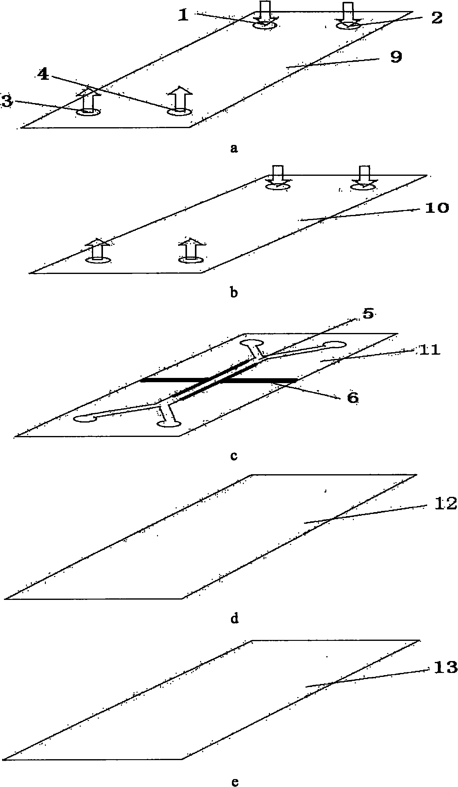
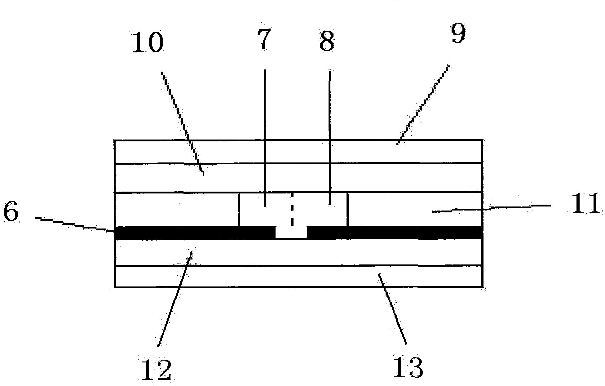
[0044] The material of the upper cover layer 9 of the single cell 14 is polycarbonate, and the specific size parameters are as follows: length × width × thickness = 50 × 30 × 2mm, the inlet of the positive electrolyte of the single cell 1, the inlet of the negative electrolyte of the single cell 2. The diameter of the electrolyte outlet 3 of the positive electrode of the single cell and the electrolyte outlet 4 of the negative electrode of the single cell is 4 mm.

[0045] The material of the single cell upper liner layer 10 of the single cell 14 is PDMS, and the specific size parameters are as follows: length × width × thickness = 50 × 30 × 5mm, and the four corners of the single cell upper liner layer 10 are provided with and single cell upper seals. On the cover layer 9, the single-cell positive electrolyte inlet 1, the single-cell negative electrolyte inlet 2, the single-cell positive electrolyte outlet 3 and the single-cell negative electrolyte outlet 4 are positioned on t...

Embodiment 2

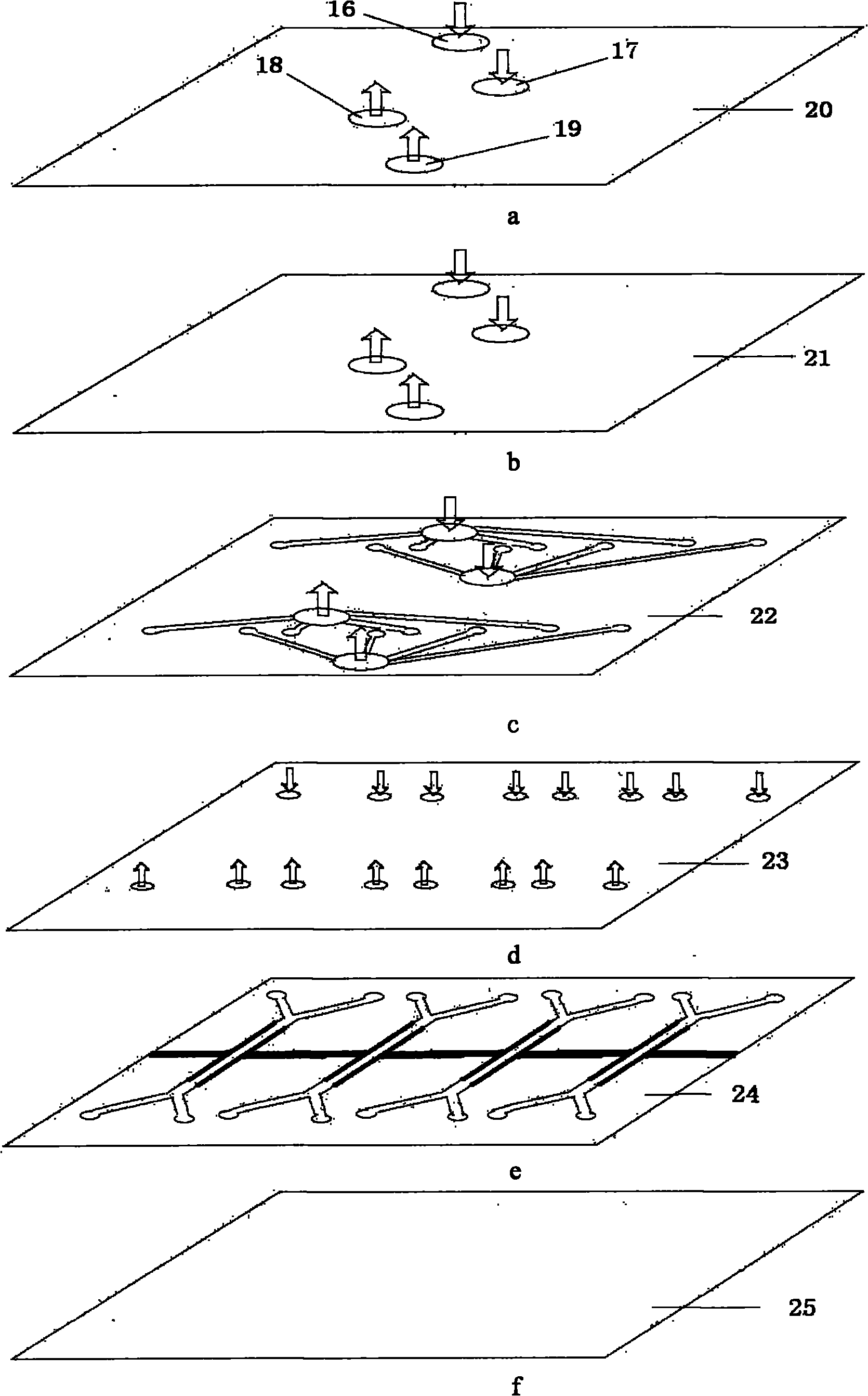
[0059] The material of the cover layer 20 on the battery stack of the battery stack 15 is polycarbonate, and the specific size parameters are as follows: length×width×thickness=200×100×2 mm, and the diameters of the four inlets and outlets are all 6 mm.

[0060] The material of the first backing layer 21 of the battery stack 15 is PDMS, and the specific size parameters are as follows: length×width×thickness=200×100×5mm, and the diameters of the four inlets and outlets are all 6mm.

[0061] The material of the first flow channel layer 22 of the battery stack 15 is PDMS, and the specific size parameters are as follows: length×width×thickness=200×100×0.5mm, the positive electrode of the first flow channel layer set in the middle of the first flow channel layer 22 of the battery stack The diameters of the electrolyte inlet, the negative electrolyte inlet of the first channel layer, the positive electrolyte outlet of the first channel layer and the negative electrolyte outlet of the...


PUM

PropertyMeasurementUnit
thicknessaaaaaaaaaa
thicknessaaaaaaaaaa
diameteraaaaaaaaaa

Abstract

The invention discloses a microfluidic liquid flow energy-storage single cell and a cell stack. The single cell comprises a single cell electrode, an anode electrolyte, a cathode electrolyte, a single cell upper capping layer, a single cell upper liner layer, a single cell flow path layer, a single cell lower liner layer and a single cell lower capping layer; the single cell upper capping layer, the single cell upper liner layer, the single cell flow path layer, the single cell lower liner layer and the single cell lower capping layer are adhered into a whole in sequence; four corners of the single cell are provided with a single cell anode electrolyte inlet, a single cell cathode electrolyte inlet, a single cell anode electrolyte outlet and a single cell cathode electrolyte outlet; a single cell microfluidic path of the single cell is provided with a single cell electrode; the single cell microfluidic path is communicated with the single cell anode electrolyte inlet, the single cell cathode electrolyte inlet, the single cell anode electrolyte outlet and the single cell cathode electrolyte outlet; and the anode electrolyte and the cathode electrolyte are filled in the single cell microfluidic path. The invention provides a cell stack formed by connecting the single cells in series, in parallel, or in series and parallel.

Description

technical field [0001] The invention relates to an energy storage battery, more specifically, to a liquid flow energy storage battery with a microfluidic structure, not only to a single battery but also to a battery stack composed of single batteries. Background technique [0002] Liquid flow energy storage batteries have the advantages of high energy conversion efficiency, long service life, adjustable capacity according to optimization requirements, environmental protection, and safety. One of the ways to develop prospects. [0003] However, current flow energy storage batteries still have some technical problems, for example, the batteries operate at low current densities. At present, the working current density of the liquid flow energy storage battery is low (<100mA / cm2), which is only one tenth of the working current density of the proton exchange membrane fuel cell, resulting in a large battery module, a large demand for materials, and high costs. . This is main...

Claims


Application Information

Patent Timeline
Patent Type & Authority Applications(China)
IPC IPC(8): H01M8/18H01M10/36H01M8/04H01M8/24H01M8/02H01M8/2465
CPCY02E60/528Y02E60/10Y02E60/50
Inventor 左春柽张舟
Owner JILIN UNIV
Learn More