Convection heating control method of electromagnetic oven and heating control device

A heating control device and convection heating technology, applied in the direction of induction heating control, induction heating device, induction heating, etc., can solve the problems of not raising, energy waste, and induction cooker can not be adjusted, and achieve the effect of promoting tumbling and even heating of food

Inactive Publication Date: 2010-08-18
JOYOUNG CO LTD
View PDF1 Cites 31 Cited by
  • Summary
  • Abstract
  • Description
  • Claims
  • Application Information

AI Technical Summary

Problems solved by technology

This technical solution proposes the possibility of solving the above-mentioned technical problems from the perspective of hardware configuration, but does not propose a specific technical solution for the ...

Method used


Image

  • Convection heating control method of electromagnetic oven and heating control device
  • Convection heating control method of electromagnetic oven and heating control device
  • Convection heating control method of electromagnetic oven and heating control device

Examples


Embodiment 1

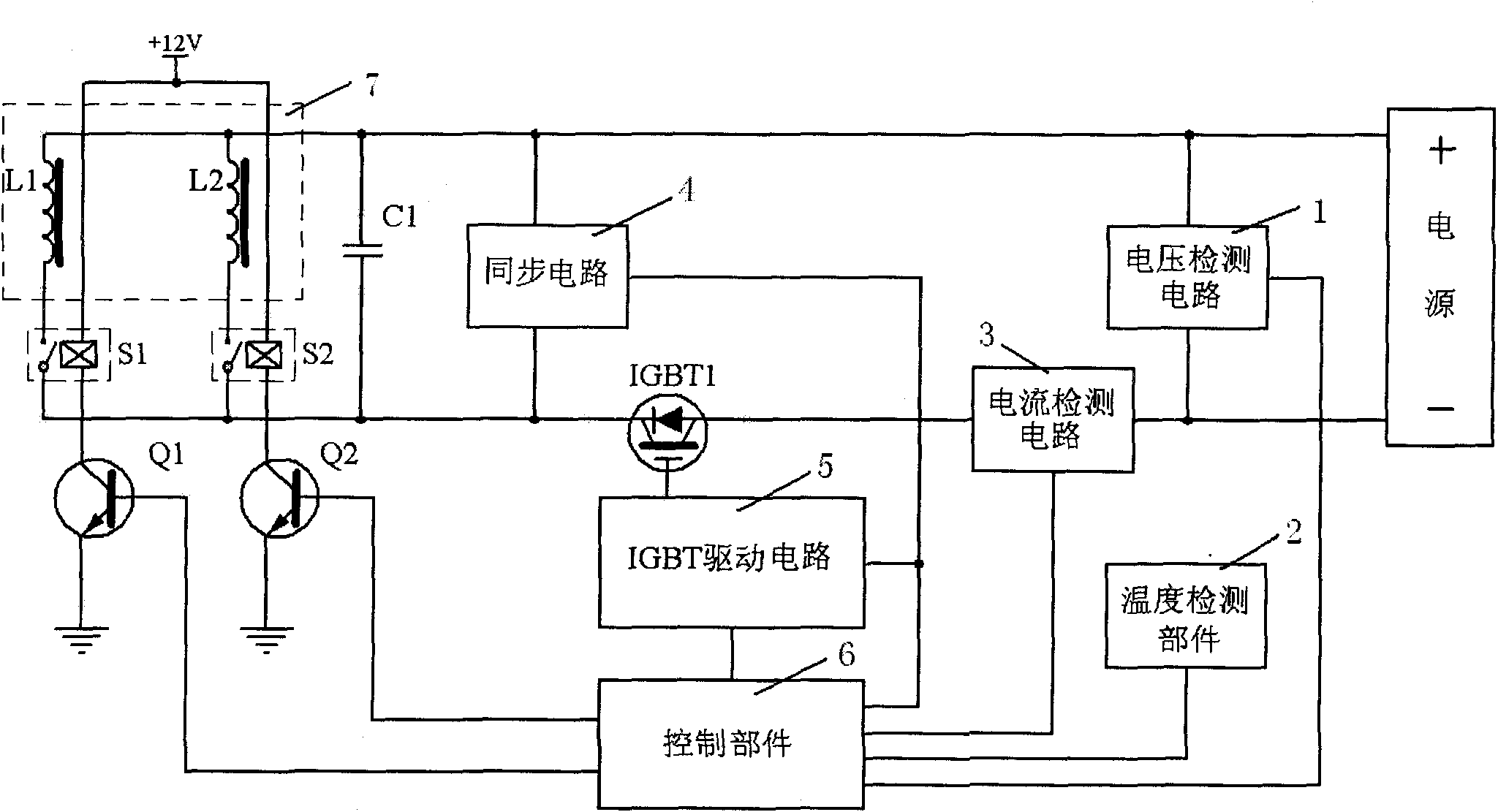
[0023] refer to figure 1 As shown, it is a schematic structural diagram of the heating control device according to the first embodiment of the present invention. The heating control device includes a control part 6 and a heating part 7. The heating part 7 includes at least two independently controllable electromagnetic coils L1 and L2. The control unit 6 includes a main controller, a timer and a preset memory, and the control unit 6 is electrically connected to the voltage detection circuit 1 , the temperature detection unit 2 , the current detection circuit 3 , the synchronization circuit 4 and the IGBT drive circuit 5 respectively. Wherein the voltage detection circuit 1 is connected with the power supply for detecting voltage conditions, and the voltage detection circuit 1 is also connected with the control unit 6 to input a voltage signal to the control unit 6; the temperature detection unit 2 is connected to the control unit 6 to the control unit 6 Input the real-time pot...

Embodiment 2

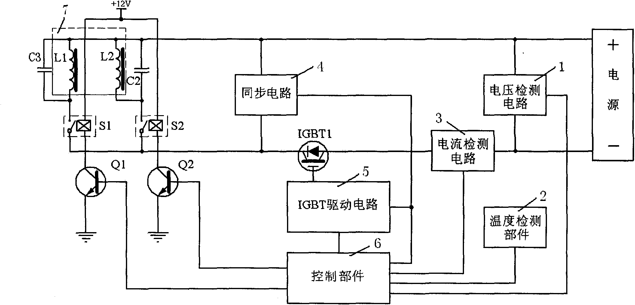
[0025] refer to figure 2 As shown, it is a schematic structural diagram of the heating control device of the second embodiment of the present invention. The difference between it and the first embodiment is that the filter capacitors C3 and C2 are connected in parallel at the two ends of the coils L1 and L2 respectively, so that the induction cooker can achieve a lower 300w low power or even lower power for continuous low power heating, effectively saving energy.

Embodiment 3

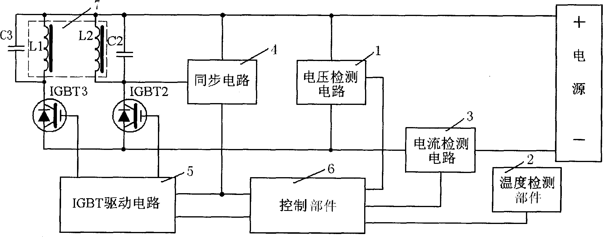
[0027] refer to image 3 As shown, it is a schematic structural diagram of the heating control device of the third embodiment of the present invention. The difference between it and the second embodiment is that the insulated gate bipolar power transistors IGBT3 and IGBT2 are used instead of the relays S1 and S2 to control the first coil L1 and the first coil L1 respectively. The heating operation of the second coil L2, and the drive transistors Q1 and Q2 are used to drive the on and off of S1 and S2 in the circuit, so they are discarded at the same time as the relays S1 and S2. In addition, since the heating operation of the power tube control coils L1 and L2 is directly set, the IGBT1 can be omitted at the same time to save cost. The technical solution of this embodiment uses a power tube instead of a relay to directly control the heating of the coil disk, which improves the reliability of the circuit and reduces the current consumption of the switching power supply.

[002...


PUM


Abstract

The invention discloses a convection heating control method of an electromagnetic oven, which is realized on the basis of a heating control device. The heating control device comprises a temperature detecting member, a heating member and a control member, wherein the heating member comprises at least two independent control electromagnetic coils, and the control member comprises a main controller, a timer and a presetting memory. The convection heating control method includes a heating-up stage A and a convection heating stage B. In addition, the invention aims to provide the heating control device for realizing the convection heating control method of the electromagnetic oven. Compared with the prior art, the invention controls the heating power proportioning of electromagnetic trays to drive a plurality of electromagnetic coils to alternatively and circularly heat a pot through distinguishing the volumes of heated foods and controls the heating coils in different positions to alternatively heat to enable the heated points of the pot to be changed along with the heating coils so that liquid in the pot is promoted to boil and convect, the foods are heated without blind angles and are uniformly heated, the nutriments of the foods can also be fully mixed, and the foods can be fully seasoned.

Description

technical field [0001] The invention relates to the technical field of induction cooker heating control, in particular to a convection heating control method and a heating control device for an induction cooker. Background technique [0002] As a new type of cooker in the kitchen utensils market, the induction cooker breaks the traditional open fire cooking method and adopts the heating principle of magnetic field induction current, so that the utensil itself can heat itself at high speed, and is used to heat and cook food, so as to achieve the purpose of cooking. At present, there are more and more users who cook, stew and stew with an induction cooker, and with the continuous improvement of living standards, people's requirements for food nutrition are also getting higher and higher. In the process of cooking and stewing food, the existing induction cooker mainly adopts a low-power heating control method, and the heating position of the pot remains unchanged in this heatin...

Claims


Application Information

Patent Timeline
IPC IPC(8): H05B6/06H05B6/12
CPCY02B30/762
Inventor 朱泽春乔中义
Owner JOYOUNG CO LTD
Why Eureka
Try Eureka