Engineering driller

A technology for engineering drilling rigs and drill pipes, which is applied in infrastructure engineering, drilling equipment, earthwork drilling and production, etc. It can solve the problems of difficult machining of vertical shafts, short moving strokes of vertical shafts, and poor stability, so as to reduce accidents in holes and correct holes. The effect of convenient positioning and enhanced stability

Inactive Publication Date: 2012-08-01
CHONGQING EXPLORATION MACHINER FACTORY
View PDF0 Cites 0 Cited by
  • Summary
  • Abstract
  • Description
  • Claims
  • Application Information

AI Technical Summary

Problems solved by technology

[0004] The engineering drilling rig of the above-mentioned structure mainly has the following deficiencies: 1. The output parts of the vertical shaft and the chuck are not directly fixed on the support column as power output components, but are fixed on the piston rods of the two feed cylinders. The construction stability of bored piles is stable, and the vertical shaft used for large torque transmission is too long to be processed, so the moving stroke of the vertical shaft is short, only between 0.5 and 0.6 meters, and the drilling distance of the active drill pipe for one-time loading and unloading of cast-in-place piles is short; 2. The active drill rod is only positioned by the piston rods of the two oil cylinders in the axial direction, the stability is poor, the drilling accuracy is not high, and accidents such as drill sticking are prone to occur; 3. The chuck is set above the vertical shaft, and each When clamping the active drill pipe, the operator must climb to the top of the winch to perform chuck clamping operation, which is not safe and time-consuming; 4. The active drill pipe is driven by a group of drill pipe motors, clutches and reducers , while the hoist is driven by another set of hoisting motor, clutch and reducer, therefore, there are relatively many devices, which occupy a large space and are expensive; 5. All devices are fixedly installed on the frame base, and there is no relative sliding between each other , one-time operation is small

Method used


Image

  • Engineering driller
  • Engineering driller
  • Engineering driller

Examples


Embodiment Construction

[0027] The present invention will be described in further detail below in conjunction with the accompanying drawings and specific embodiments.

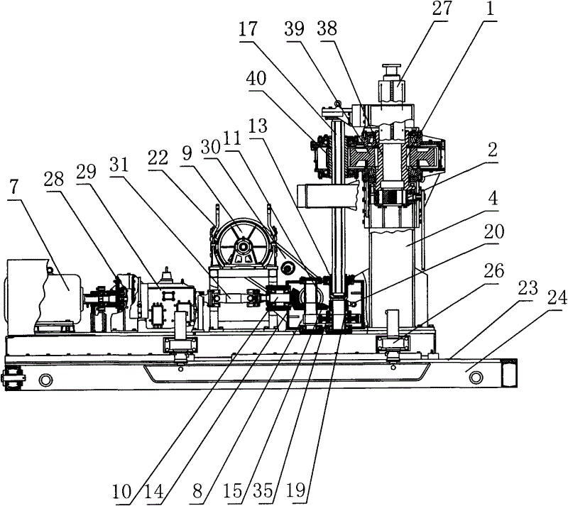
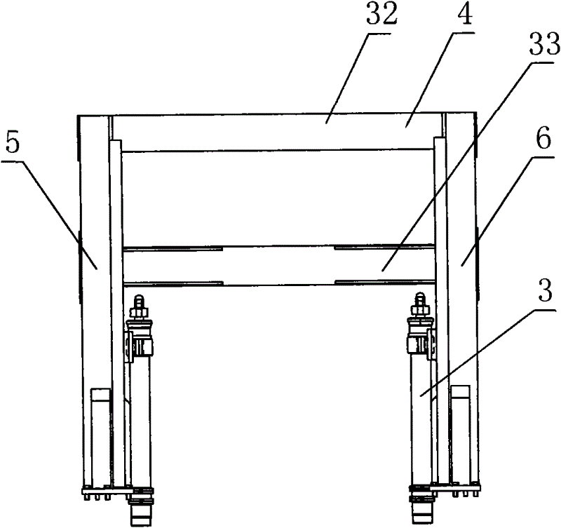
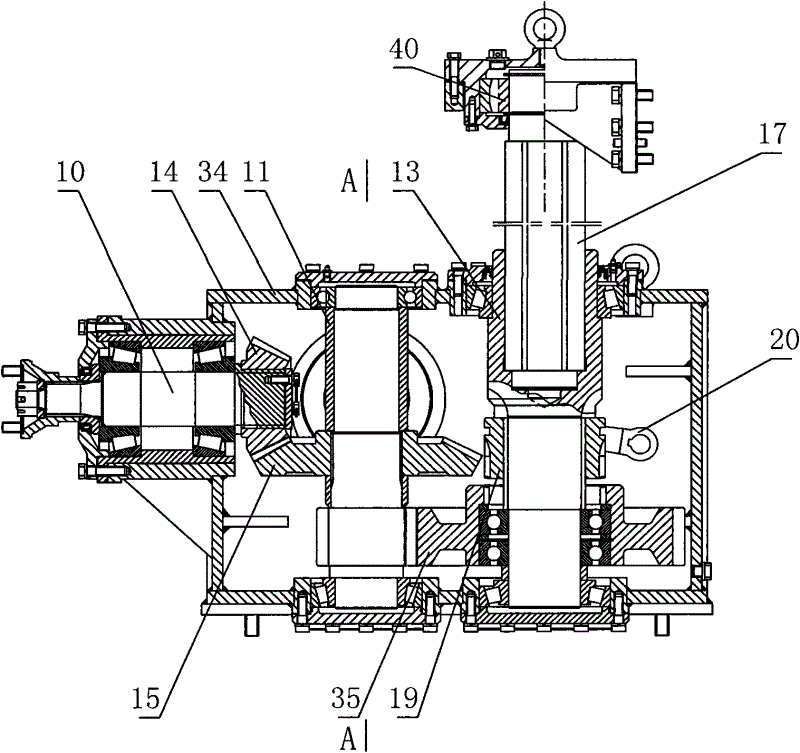
[0028] figure 1 It is a structural schematic diagram of the present invention, figure 2 It is a structural schematic diagram of the gantry frame in the present invention, as shown in the figure: the engineering drilling rig includes a base 24, a frame seat 23, a motor 7, a clutch 28, a reducer 29, a commutator 8, a sprocket box 30, a hoist 9, and a gantry Frame 4, power head 1, driving drill rod 27, feeding oil cylinder 3, hexagonal rotating shaft 17 and the chuck 2 that the piston rod of driving drilling rod 27 relative feeding oil cylinder 3 is vertically fixed. The frame seat 23 is pressed on the left and right sides of the base 24, and can be slidably fitted on the left and right sides of the base 24 with a single degree of freedom. Described motor 7, clutch 28, speed reducer 29, commutator 8, winch 9 and gantry frame 4 are fix...


PUM


Abstract

The invention discloses an engineering driller comprising a power head, a driving drill rod, two feeding oil cylinders, a portal frame and a chuck for vertically fixing the driving drill rod opposite to a stand, wherein the driving drill rod vertically passes through a main shaft of the power head, the portal frame comprises a left vertical post and a right vertical post, and both sides of the power head are respectively clamped on the left vertical post and the right vertical post and are in single-freedom sliding fit with vertical posts at the corresponding side; and the two feeding oil cylinders are respectively fixed and arranged at the bottoms of the left vertical post and the right vertical post, piston rods of the feeding oil cylinders are vertically and upwards fixed with the power head below which the chuck is arranged, and the driving drill rod is clamped in the chuck. A power head support frame of the engineering driller adopts a portal vertical post structure, both sides of the power head are respectively clamped on the left vertical post and the right vertical post of the portal frame, the power head moves up and down through the feeding oil cylinders, the stroke can be about 1 meter, and therefore, the engineering driller has high precision of vertical movement; because the chuck is arranged below the power head, an operator can directly operate the engineering driller without climbing the driller; and the engineering driller has the advantages of safety, convenience and high efficiency.

Description

technical field [0001] The invention relates to building construction equipment, in particular to an engineering drilling rig. Background technique [0002] The engineering drilling rig is a drilling rig used for the construction of large-diameter cast-in-situ piles in high-rise buildings, ports, docks, dams, electric power, bridges and other projects. [0003] In the prior art, an engineering drilling rig includes a frame base, a drill rod motor, a clutch, a speed reducer, a winch motor, a winch, a vertical shaft, a chuck, a support column and a driving drill rod. The power is transmitted from the gear shaft to the vertical shaft, and then through the chuck to the active drill pipe that passes through the center of the vertical shaft vertically. The two sides of the vertical shaft and the chuck are fixedly installed on the piston rods of the two vertical upward feed cylinders respectively. The vertical shaft needs to move up and down when transmitting the feed force of the...

Claims


Application Information

Patent Timeline
Patent Type & Authority Patents(China)
IPC IPC(8): E21B7/02E21B6/04E02D5/34
Inventor 李剑
Owner CHONGQING EXPLORATION MACHINER FACTORY
Why Eureka
Try Eureka