Device and method for self-piercing riveting of half-hole rivet loaded by pulse magnet field force

A pulsed magnetic field and self-piercing riveting technology, applied in the field of self-piercing riveting devices for semi-hole rivets, can solve the problems of difficult automation, complex riveting process, poor riveting quality, etc., and achieve full-position operation, automatic and semi-automatic production, The effect of stable riveting quality, improving strength and fatigue life

Inactive Publication Date: 2010-09-01
HARBIN INST OF TECH
View PDF5 Cites 41 Cited by
  • Summary
  • Abstract
  • Description
  • Claims
  • Application Information

AI Technical Summary

Problems solved by technology

[0004] The purpose of the present invention is to provide a device and method for self-piercing riveting of half-hole rivets loaded by pulsed magnetic field force, so as to solve the requirement of adopting the traditional stamping self-riveting riveting process to pre-pierce the riveted components first, and then connect them with rivets , complex riveting process, poor riveting quality, low efficiency and difficult automation

Method used


Image

  • Device and method for self-piercing riveting of half-hole rivet loaded by pulse magnet field force
  • Device and method for self-piercing riveting of half-hole rivet loaded by pulse magnet field force

Examples


specific Embodiment approach 1

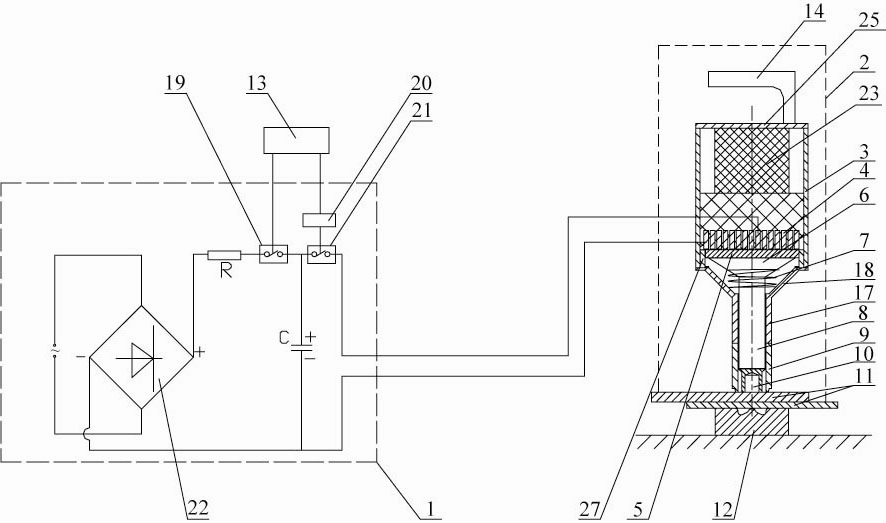
[0009] Specific implementation mode one: combine figure 1 Describe this embodiment mode, a kind of half-hole rivet self-piercing riveting device that utilizes the pulse magnetic force loading of this embodiment to be made up of electromagnetic riveting gun 2, die 12, low-voltage electromagnetic riveting device 1 and control box 13; Electromagnetic riveting gun 2 is made up of The primary coil 4, the driving plate 5, the stress wave modulator 6, the compression spring 7, the punch 8, the electromagnetic riveting gun handle 14, the shock absorber 23, the positioning ring 27 and the riveting gun shell; Axially through the cavity, the shell of the riveting gun is composed of a large cylindrical tube 3 with a large outer diameter, a front cover, a rear cover 25 and a fastening sleeve 9, and the front cover is composed of a frustum-shaped tube 18 and a punch guide tube 17. The handle 14 of the electromagnetic riveting gun is fixedly connected with the back cover 25, and the punch gu...

specific Embodiment approach 2

[0010] Specific implementation mode two: combination figure 1 Describe the present embodiment, the low-voltage electromagnetic riveting device 1 of the present embodiment is made up of electromagnetic riveting charging switch 19, capacitor group C, current limiting resistor R, rectifier 22, high-frequency thyristor discharge switch 21 and high-voltage pulse generator 20; terminals are respectively connected to the two AC voltage input terminals of the rectifier 22, the DC voltage positive output terminal of the rectifier 22 is connected to one end of the current limiting resistor R, and the other end of the current limiting resistor R is connected to one end of the electromagnetic riveting charging switch 19, and the electromagnetic riveting The other end of the charging switch 19 is respectively connected with one end of the high-frequency thyristor discharge switch 21 and the positive end of the capacitor bank C, the other end of the high-frequency thyristor discharge switch ...

specific Embodiment approach 3

[0011] Specific implementation mode three: combination figure 1 The present embodiment will be described. The shock absorber 23 of the present embodiment is a shock absorber spring, rubber or rubber spring. Select as needed. Others are the same as the first or second embodiment.


PUM


Abstract

The invention discloses a device and a method for the self-piercing riveting of a half-hole rivet loaded by a pulse magnet field force, which relate to the device and the method for the self-piercing riveting of the half-hole rivet and aim to solve the problem that a conventional punching self-riveting process has the problems of complex riveting process, bad riveting quality and low efficiency in the pre-punching of a riveting component. A punch head is arranged below a stress wave modulator; a female die is arranged under an electromagnetic riveting gun; a control box controls the on / off of an electromagnetic riveting charging switch of a low-voltage electromagnetic riveting device and is connected with the signal input end of a high-voltage pulse generator of the low-voltage electromagnetic riveting device; and the signal output end of the high-voltage pulse generator is used for controlling the on / off of a high-frequency thyristor discharging switch of the low-voltage electromagnetic riveting device. The method comprises the following steps that: firstly, a capacitor bank is charged; secondly, a discharging loop is switched on and the capacitor bank is discharged to apply the action of an axially downward pulse load to a driven piece; and finally, the stress wave modulator is amplified and acts on the half-hole self-punching rivet through the punch head to realize self-punching riveting. The device and the method are used for the self-punching riveting of a connected piece.

Description

technical field [0001] The invention relates to a half-hole rivet self-piercing riveting device and method, and belongs to the technical field of realizing mechanical connection through stamping deformation. Background technique [0002] Half-hole rivet self-piercing riveting is a form of punching self-piercing riveting. Stamping self-riveting riveting is a connection method in which the connected parts have no prefabricated holes and the rivets with connecting elements are processed from both sides. In this process form, the pre-punching necessary for the traditional rivet connection method is replaced by the shearing and stamping process of the rivet. Under the push of the punch, the half-hole rivet pierces the upper sheet, and under the joint action of the die and the punch, the tail of the rivet opens in the metal of the lower layer in the shape of a bell mouth, forming a firm riveting point, so as to achieve self- The purpose of the lock connection. Compared with spo...

Claims


Application Information

Patent Timeline
Patent Type & Authority Applications(China)
IPC IPC(8): B21J15/24B21J15/38
CPCB21J15/025B21J15/24
Inventor 于海平李春峰孙立强江洪伟
Owner HARBIN INST OF TECH
Why Eureka
Try Eureka