Cylinder-deactivation control method and device of electronic-control fuel-injection multi-cylinder internal-combustion engine

A multi-cylinder internal combustion engine and fuel injection technology, which is applied in engine control, mechanical equipment, machines/engines, etc., can solve the problem of increasing fuel consumption, inability to adapt, and difficulty in meeting the requirements of the effective working conditions of the catalytic treatment device. and other issues, to achieve the effect of reducing harmful gas emissions, improving service life, and reducing the number of frequent short-term operations

Inactive Publication Date: 2010-09-01
塞尔福(厦门)工业有限公司
View PDF8 Cites 30 Cited by
  • Summary
  • Abstract
  • Description
  • Claims
  • Application Information

AI Technical Summary

Problems solved by technology

The above cylinder deactivation control scheme may make it difficult for the temperature of the catalytic treatment device and the oxygen concentration in the exhaust to meet the effective working conditions of the catalytic treatment device
U.S. Patent US4129109 discloses a method for reducing the switching shock, that is, switching is performed when it is close to full load or close to idle speed, but the frequent switching shock is still inevitable, and it cannot adapt to the fast accelerator without necessarily adding to the full load. when high torque is required
US Patent No. 4,467,602 discloses a method for controlling the temperature of an exhaust catalytic treatment device with deactivated cylinders, but the enrichment control strategy will increase fuel consumption

Method used


Image

  • Cylinder-deactivation control method and device of electronic-control fuel-injection multi-cylinder internal-combustion engine
  • Cylinder-deactivation control method and device of electronic-control fuel-injection multi-cylinder internal-combustion engine
  • Cylinder-deactivation control method and device of electronic-control fuel-injection multi-cylinder internal-combustion engine

Examples


Embodiment Construction

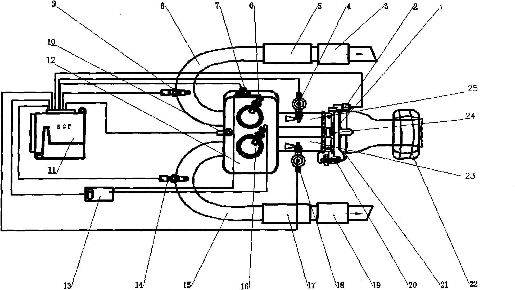
[0044] exist figure 1 In the shown embodiment, the multi-cylinder internal combustion engine is a gasoline engine with dual-cylinder electronically controlled fuel intake port injection, and the parts shared by the two cylinders include: air filter 22, throttle position sensor 2, throttle operating runner 20, rotating speed and Angle sensor 7, engine body 12, engine temperature sensor 10, electronic control unit (ECU) 11, ignition energy supply device 13, load operation runner 20, and the components used independently by the two cylinders include, the independent components of the first cylinder system include : Throttle body 1, intake port 25, fuel injector 4, spark plug 6, exhaust pipe 8, oxygen sensor 9, exhaust catalytic treatment device 5, exhaust muffler 3, etc. The independent components of the second cylinder system include: Valve body 21, intake port 23, fuel injector 18, spark plug 16, exhaust pipe 15, oxygen sensor 14, exhaust catalytic treatment device 17, exhaust ...


PUM


Abstract

The invention relates to cylinder-deactivation control method and device of an electronic-control fuel-injection multi-cylinder internal-combustion engine. The cylinder-deactivation control method of the electronic-control fuel-injection multi-cylinder internal-combustion engine comprises the following steps of: (1) collecting a position sensor signal of a throttle of a throttle device by an ECU (Electronic-Control Unit) and calculating the size and the change rate of the position sensor signal; (2) collecting the temperature of an engine or the temperature of engine cooling liquid by the ECU; (3) measuring the rotating speed of the engine by the ECU; (4) calculating the lasting time of the latest working mode by the ECU; and (5) logically calculating a working mode of the next clock by the ECU according to the information and the preset working mode judging conditions, wherein the working modes of the next clock comprise (a) a full-cylinder working mode, (2) a partial cylinder-deactivation working mode and (3) a full oil-break mode. On the size and change rate plane of the position sensor signal, the operation state of the engine is divided into three areas by two boundary lines, i.e. a full-cylinder working area, a partial cylinder-deactivation working area and a hysteresis area. The invention can save fuel consumption of the engine under a normal working condition due to partial cylinder-deactivation work and can enhance the dynamic feeling of a vehicle while being forcefully and rapidly throttled.

Description

technical field [0001] The invention relates to an electronically controlled fuel injection multi-cylinder internal combustion engine, in particular to a spark ignition internal combustion engine device and a cylinder deactivation control method for an electronically controlled intake port / intake pipe fuel injection that realizes partial cylinder deactivation by stopping fuel injection. Background technique [0002] For multi-cylinder internal combustion engines, especially spark ignition multi-cylinder internal combustion engines that adjust the load through air intake throttling, when working under low load conditions, the fuel consumption rate is much higher than that under heavy loads due to reasons such as low mechanical efficiency and combustion deterioration. Therefore, the load of the remaining part of the working cylinders can be increased by stopping the operation of some cylinders, so that the fuel consumption rate of the multi-cylinder internal combustion engine c...

Claims


Application Information

Patent Timeline
Patent Type & Authority Applications(China)
IPC IPC(8): F02D17/02F02D11/10
Inventor 杨延相刘昌文郗大光
Owner 塞尔福(厦门)工业有限公司
Why Eureka
Try Eureka