
Ball grinder available for solid state reaction of powder

A solid-state reaction and ball mill technology, applied in grain processing, etc., can solve problems such as uneven particle size, limited mechanical energy, and easy fatigue and fracture, and achieve excellent physical and chemical properties, high degree of automation, and continuity.

Inactive Publication Date: 2010-09-08
BEIJING UNIV OF CHEM TECH
View PDF2 Cites 24 Cited by
  • Summary
  • Abstract
  • Description
  • Claims
  • Application Information

AI Technical Summary

Problems solved by technology

Obviously, the existing vertical ball mill is difficult to meet the above requirements. Because the supporting shaft of the ball mill pot is supported by a cantilever beam, the alternating bending stress at the support is large, and it is easy to fatigue and fracture. Therefore, the maximum speed of the equipment can only reach 600 rpm, and the internal structure of the ball mill is simple, the steel balls only do simple centrifugal motion, so the mechanical energy generated by the steel balls is limited, and generally can only be used for grinding raw material particles. In addition, because ordinary ball mills do not have an effective temperature adjustment structure , it is impossible to eliminate the high temperature caused by the collision and friction between the material, the grinding ball and the tank wall, resulting in the accumulation and agglomeration of the material, which affects the solid state reaction effect of the material and the physical and chemical properties of the final product, uneven particle size, quality Not stable enough; in addition, there is no control and adjustment structure for the reaction atmosphere in the tank

Method used


Image

  • Ball grinder available for solid state reaction of powder
  • Ball grinder available for solid state reaction of powder

Examples


Embodiment 1

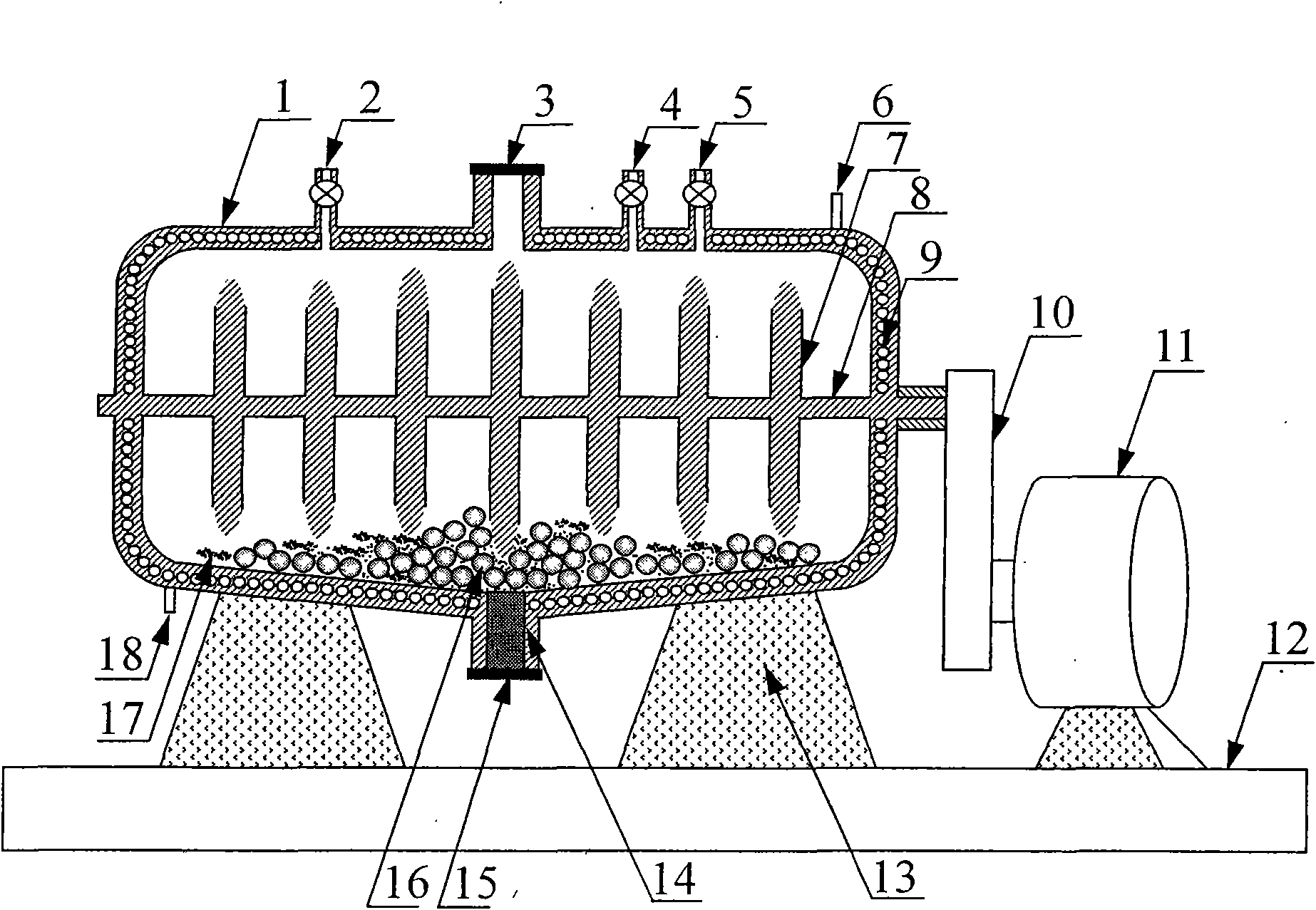
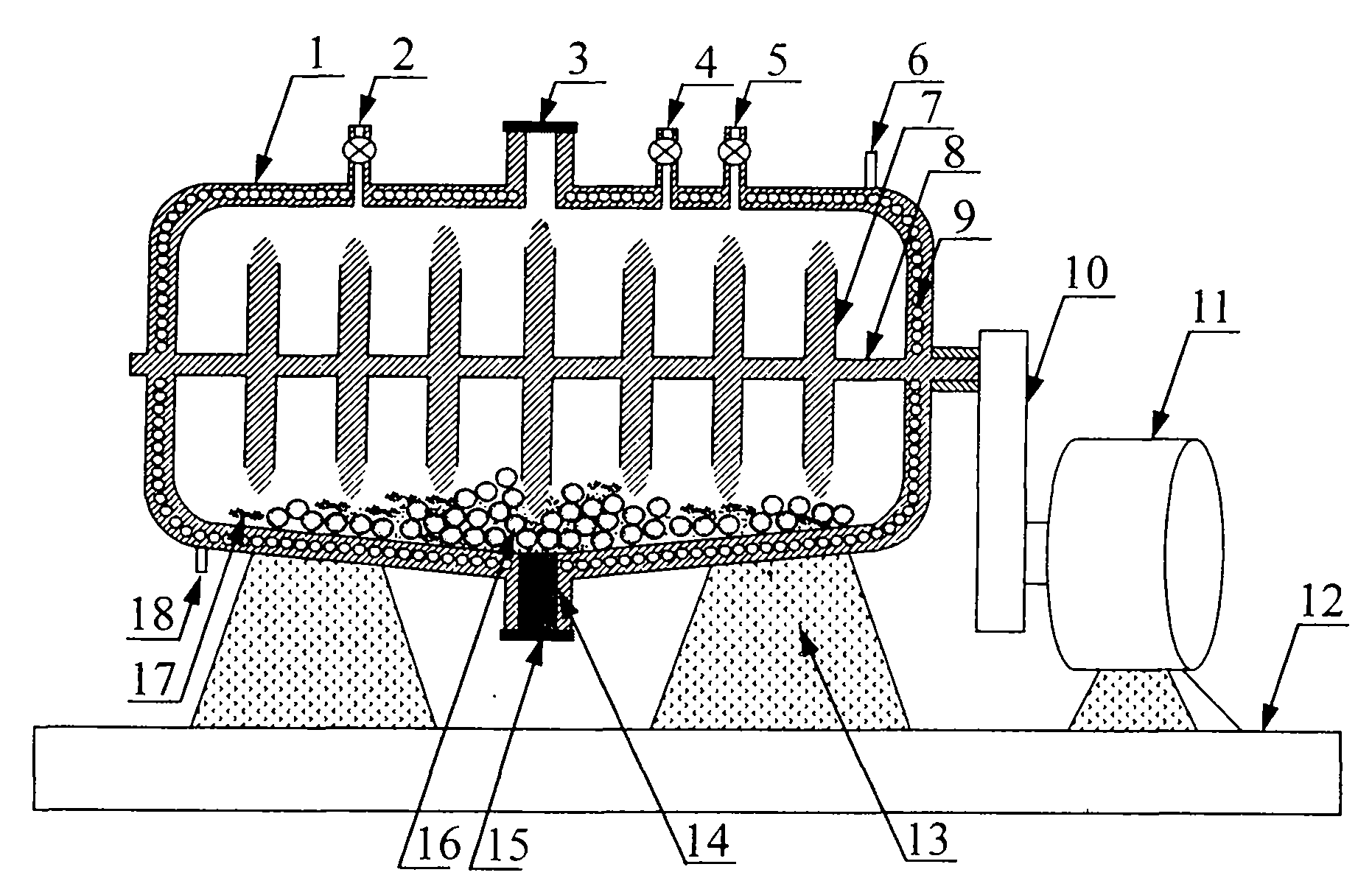
[0020] Preparation of perovskite type LaMnO with ball mill of the present invention 3 Composite oxide, wherein the diameter of the ball mill cylinder is 1 meter, the length of the cylinder is 2 meters, the slope of the bottom of the cylinder is 20 degrees, and the number of paddles is 8. According to the molecular formula LaMnO, the oxides of lanthanum and manganese 3 Weigh, mix, and transfer to the grinding tank with the atomic molar ratio shown in , the amount of material added is 10 kg; place stainless steel balls about 5 times the weight of the mixed material; start the motor, and run at a frequency of 1000 times per minute , so that the steel ball produces high-speed irregular motion, and squeezes and kneads the material. The process is dry grinding, and the grinding process continuously replenishes air into the grinding jar. Use circulating water as cooling medium to control the grinding temperature in the range of 3 Composite oxide, the specific surface area can reach...


PUM


Abstract

The invention relates to a ball grinder available for the solid state reaction of powder, which mainly comprises a ball grinding cylinder, an electromotor, a driving device, a grinding ball and a material inlet and outlet, wherein the horizontal type ball grinding cylinder is fixedly supported on a bracket; a jar is internally provided with the girding ball; the center of the ball grinding cylinder is provided with a rotatable main shaft; the main shaft is driven by the electromotor through the driving device to rotate; the main shaft is provided with a blade, wherein the rotating speed of the blade is 300-2000 r / min; the mechanical energy is transmitted to the grinding ball through the beating of the blade, so that the grinding ball can irregularly move with high speed; the bottom of theball grinding cylinder is in the shape of gradient with 0-30 degrees from the two ends to the center; the jar body of the ball grinding cylinder is provided with a cooling sleeve and an inlet and an outlet of cooling medium; and the jar body of the ball grinding cylinder is provided with an air exhausting opening and an air inlet. The ball grinder can lead the grinding ball to generate higher mechanical energy to provide high energy for inducing the solid state reaction among materials, thereby smashing, grinding and dispersing the materials and directly reacting to generate nanometer composite oxide.

Description

technical field [0001] The invention relates to a powder processing equipment, in particular to a ball mill, which can be used for ultrafine powder grinding, and can also be used for powder solid-state chemical reaction, such as grinding to prepare nano-composite oxides. technical background [0002] Ball mill is a commonly used powder processing equipment, which is widely used in the dispersion, grinding, mixing and mechanical alloying of various materials. Traditional ball mills are mostly vertical (such as the QM-1SP developed by Nanjing University, Chinese patent, patent No. ZL 02220259.5), and its structure is that several ball milling tanks are symmetrically installed on the turntable vertical to the ground. Under the action of centrifugal force, the movement will grind the powder in the tank to achieve the purpose of crushing the material. Chinese patent 200610045805.3 discloses a mechanical grinding technology, which proposes that under the action of specific atmosp...

Claims


Application Information

Patent Timeline
Patent Type & Authority Applications(China)
IPC IPC(8): B02C17/10B02C17/18
Inventor 张润铎陈标华
Owner BEIJING UNIV OF CHEM TECH
Learn More