High-energy low-repetition-frequency fiber laser

A technology of fiber laser and repetition rate, which is applied in cladding optical fiber, optical waveguide and light guide, instrument, etc., can solve the problems of lengthening laser, good mode-locking effect, and high price, so as to improve single pulse energy, facilitate broadening, and simplify structure effect

Inactive Publication Date: 2010-09-08
PEKING UNIV
View PDF0 Cites 31 Cited by
  • Summary
  • Abstract
  • Description
  • Claims
  • Application Information

AI Technical Summary

Problems solved by technology

However, this kind of photonic crystal fiber has great disadvantages: it is very expensive and monopolized by foreign companies (such as Crystal Fiber in Denmark), and welding is very difficult (ordinary fusion splicers cannot be welded and need to be welded by the original f

Method used


Image

  • High-energy low-repetition-frequency fiber laser
  • High-energy low-repetition-frequency fiber laser
  • High-energy low-repetition-frequency fiber laser

Examples


Embodiment 1

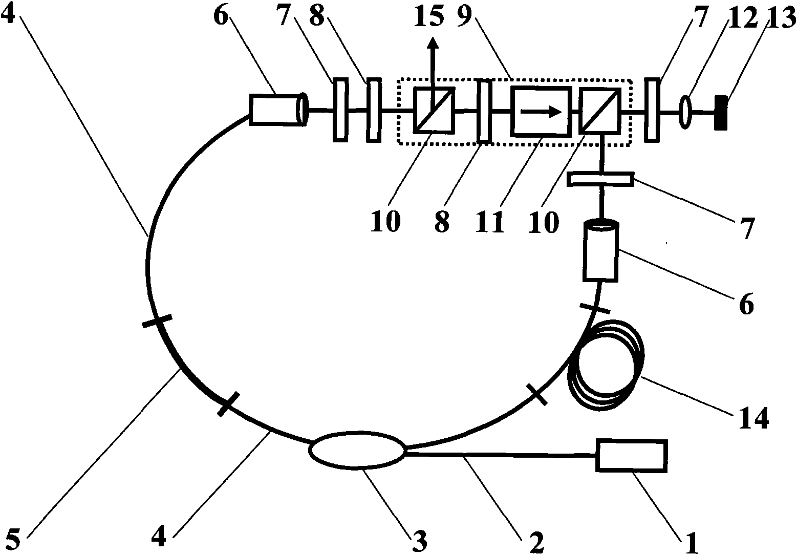
[0067] For ring cavity fiber lasers, such as figure 1Shown is a preferred embodiment of the fiber laser with high energy and low repetition rate of the present invention, in the fiber laser: the pump light source 1 used to provide the energy required to generate laser light is connected to the wavelength division multiplexer through the pump light transmission fiber 2 The wavelength division multiplexer 3 is used as a pump coupler to connect the pump light source 1 to the resonant cavity of the fiber laser to provide an energy inlet. A ring-shaped resonant cavity is formed by connecting the single-mode transmission fiber 4, the gain fiber 5 and the mode-locking device. In this embodiment, the mode locking device adopts a saturable absorber 13 , and a focusing lens 12 is connected before the saturable absorber 13 for focusing the generated laser light on the saturable absorber 13 . Since the difference between the present invention and the prior art is that the length of the s...

Embodiment 2

[0070] For ring cavity fiber lasers, such as Figure 4 Shown is another preferred embodiment of the fiber laser with high energy and low repetition rate of the present invention. Most of the devices and their connections in this embodiment are the same as those in Embodiment 1, except that this embodiment uses fiber-optic unidirectional isolation The split-type one-way space isolator 9 is replaced by a device 16, and the one-way isolator 16 is also used to make the generated laser unidirectionally transmit in the resonator to form an oscillation, and can be placed in Figure 4 The position shown can also be placed arbitrarily at the other end of the wavelength division multiplexer 3, such as Figure 4 shown by the dotted line. Two polarizing beamsplitters 10 are still connected in the resonant cavity, one of which is used as a laser output port 15 to output ultrashort pulse laser; 13. Form a T-shaped structure.

Embodiment 3

[0072] For ring cavity fiber lasers, such as Figure 5 Shown is another preferred embodiment of the fiber laser with high energy and low repetition rate of the present invention. In the fiber laser: the pump light source 1 used to provide the energy required to generate laser light is connected to the wavelength division through the pump light transmission fiber 2 The multiplexer 3, the wavelength division multiplexer 3 is used as a pump coupler to connect the pump light source 1 to the resonant cavity of the fiber laser to provide an energy inlet. A ring-shaped resonant cavity is formed by connecting the single-mode transmission fiber 4, the gain fiber 5 and the mode-locking device. In this embodiment, the mode-locking device adopts a saturable absorber 13. In this embodiment, an optical circulator 17 is used to replace the polarization splitter prism 10 in Embodiment 2. The optical circulator 17 is connected to the two ends of the single-mode transmission fiber 4 and the sat...


PUM


Abstract

The invention relates to a high-energy low-repetition-frequency fiber laser, which comprises a pump light source used for providing energy for generating laser light, a gain fiber used for providing gains, a mode locking device used for modulating the laser light so as to generate ultrashort pulses, and a single-mode transmission fiber used for laser transmission, wherein the gain fiber, the single-mode transmission fiber and the mode locking device form a resonant cavity of the fiber laser; the generated laser light is oscillated in the resonant cavity; and under the condition that the lengths of the gain fiber and the mode locking device are not increased, the length of the single-mode transmission fiber is increased according to a relation that the length L of the resonant cavity is inversely proportional to the repetition frequency frep of the fiber laser and according to the reduction of the needed repetition frequency frep. By increasing the length of the resonant cavity, the high-energy low-repetition-frequency fiber laser reduces the repetition frequency of pulses in the resonant cavity, correspondingly improves the energy of a single pulse, further simplifies the structure of an amplification system, improves the efficiency of an amplifier and effectively reduces the cost.

Description

technical field [0001] The invention relates to the field of mode-locked fiber lasers and amplifiers, in particular to a fiber laser with high energy and low repetition frequency. Background technique [0002] Mode-locked fiber laser refers to an experimental device that uses mode-locked technology to generate femtosecond and picosecond ultrashort pulses in fiber lasers. Mode-locking technology is a method of modulating a laser beam, so that different longitudinal modes of oscillation in the beam have a definite phase relationship, so that each mode can be coherently superimposed to obtain an ultrashort pulse. In general, ultrashort pulses refer to femtosecond and picosecond pulses, where 1 femtosecond = 1×10 -15 Second, 1 picosecond = 1×10 -12 Second. General mode-locked fiber lasers use semiconductor lasers as pump light sources, use special fibers doped with rare earth elements as gain fibers, use single-mode fibers as basic components in the laser cavity, and use the ...

Claims


Application Information

Patent Timeline
IPC IPC(8): H01S3/067H01S3/08G02B6/02G02F1/35
Inventor 周春蔡岳张志刚
Owner PEKING UNIV
Why Eureka
Try Eureka